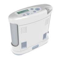
Service Manual, Inogen One G3HF
SP-519 Inogen One G3 LCD Cable Replacement
Parts Required:
1. SP-519, Cable Assembly, LCD
Tools Required:
1. T10 Torx Driver
Notes:
1. When removing screws from the device carefully set in a bin or secure area as these
screws will used to secure the replacement parts.
2. Many of the screws using on the Inogen One G3 have pre-applied loctite on the threads.
These loctite screws can be re-used up to four times before replacement screws are
required (If exceeded four uses please contact Inogen for a screw replacement kit).
1. The connectors for the LCD and User Interface Panel are delicate and should be handled
carefully. They must be inserted into the connector straight and be clean of all debris or
contamination in order to ensure proper LCD and User Interface Panel Operation.
Instructions for Removing the Housing:
Refer to “SP-502 and SP-550 Inogen One G3HF Front and Rear
Housing
Replacement
”
on Page 3. Follow steps 1-5 for “Instructions for Removing the Housing.”
Instructions for Removing the User Interface Panel:
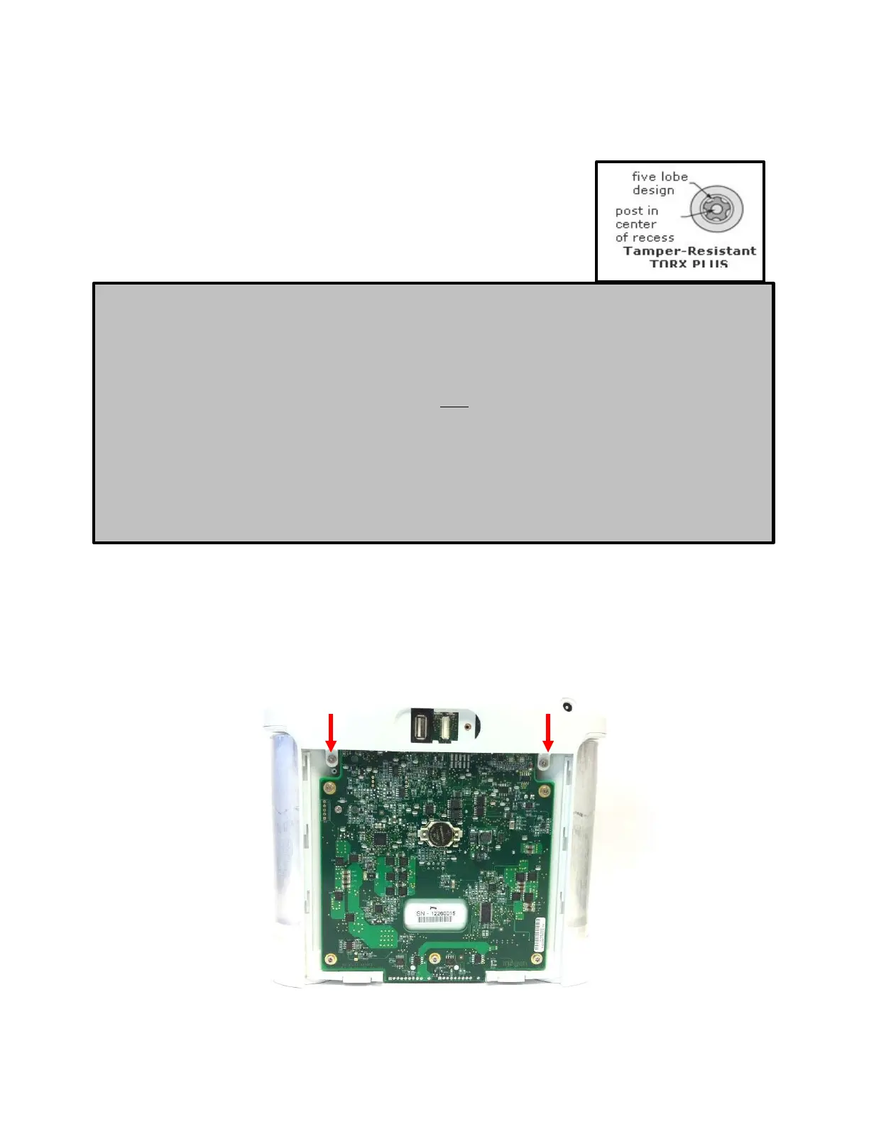
1. With the side housing removed, locate and remove the four screws that connect the user
interface panel to the chassis (Figures 1 and 2).
Figure 1: Location of rear screws
 Loading...