Service Manual, Inogen One G3HF
2. Place the LCD module against the back side of the UIP window on the new user interface
panel. Orient the LCD module so that the LCD cable connector is on the right side of the
user interface panel (as in Figure 5).
3. Re-install the two screws securing the LCD to the user interface panel, making sure that
the LCD is straight and properly aligned in the UIP window (Figure 5). Tighten screws to
5 in-lbs.
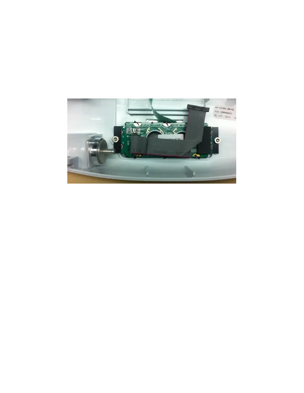
4. Reconnect the power cable to the LCD module (Figure 6). Note the location of the red
wire.
Figure 6: Orientation of LCD cable
5. Re-attach the cannula tubing to the cannula connector (Figure 4).
6. Plug the UIP cable back into the motherboard (Figure 3). Double check that the cables
are fully seated to ensure a complete connection.
7. Test the function of each button and the LCD. If anything does not work, reseat the
cables in the connectors and check for debris in the connectors.
8. Re-install the four screws that connect the user interface panel to the chassis (Figures 1
and 2). Tighten screws to 5 in-lbs.
Instructions for Replacing the Housing:
1. Place the device on its back side.
2. Seat the feet of the front housing into the corresponding grooves on the chassis (Figure
7) then push down and toward the device to secure the housing in the chassis.
 Loading...