CONFIDENTIAL
and PROPRIETARY
96-09302-00-01 revA DCR 19-030 21-Mar-2019 INOGEN ONE G5 TECHNICAL MANUAL
Page 7 of 18
this period, Inogen recommends making arrangements to bring an extra oxygen
supply.
3.1.3. Accessing Information Screen
To check usage from the device, press and hold the mode Button (bell symbol) for 5
seconds while the unit is running normally. The concentrator’s display will show the hour
meter, the unit’s serial number, and the software version installed on the device.
3.1.4. System Inspection
At the start of any maintenance visit:
1. Be sure to ask the patient if they have experienced any difficulties in operating the
equipment.
2. Be sure to ask the patient if they have observed any malfunctions or changes in
characteristics of the equipment.
3. Visually inspect the device and accessories for cracks or other damage.
4. Feel the sides of the device for vibration and listen for unusual noises, rattles, or
other signs that the device requires service.
CAUTION
Discovery of cracks or other types of external damage may be indicative of other
internal damage that may not be visible. If such external damage is discovered,
be certain to inquire as to how it occurred, and whether any changes in the
device have been noticeable since its occurrence. If you have any concern over
the safety of the device, arrange for equipment servicing.
3.1.5. Output Filter Replacement
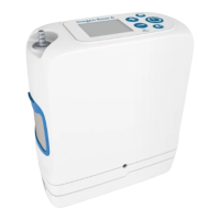
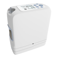
This filter is intended to protect the user from small particles in the product gas flow. The
Inogen One G5 includes an output filter conveniently located behind the removable cannula
nozzle fitting. Inogen suggests that this filter be replaced between patients.
Use the Output Filter Replacement Kit to replace the Output Filter:
1. Use the Cannula Barb Tool (included in RP-404) to access the output filter. The
tool has two prongs which mate with two indentations located on the surface of
the metal cannula barb fitting on the Inogen One G5.
2. Carefully remove the cannula fitting by unscrewing it in the counter-clockwise
direction.
3. The filter, a thin white disk, will be visible in the recess once the hose barb is
removed.
4. Remove the filter, and inspect the recess to make sure it is free of debris.
5. Install a replacement filter.
6. Carefully screw the cannula barb fitting back into the recess (clockwise) until it
bottoms out on the filter gasket. Take care to squarely screw the nozzle fitting
into the threads, and not to over tighten.
CAUTION
Failure to inspect and replace the product filter may result in the filter becoming
clogged or obstructed over time, and in reduced delivery of oxygen to the
 Loading...