Do you have a question about the InoTec CPS 220/20/J-SV/J-SKU and is the answer not in the manual?
| Brand | InoTec |
|---|---|
| Model | CPS 220/20/J-SV/J-SKU |
| Category | Controller |
| Language | English |
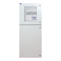
Introduction to the central battery system, covering models CPS 220/20 and CPS 220/64.
Instructions for the physical assembly and mounting of the system components.
Assembly steps for connecting electronics and battery cabinets for various system models.
Specific assembly instructions for the CPUSB 220/64/1 system.
Electrical connection details for various CPS, CPUS, and CPUSB system configurations.
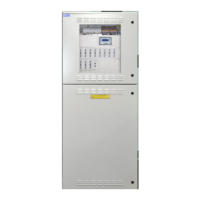
Detailed description of the TFT controller's user interface, features, and capabilities.
Settings for configuring device-specific parameters like type, destination, and blocking.
Configuration settings for the device's network connection and communication.
Procedure for learning reference values for circuits and luminaire addresses.
Steps for establishing a direct PC connection to the TFT touch controller for configuration.
Procedure for programming luminaires and change-over devices directly via the TFT Touch controller.
Requirements for initial tests of the emergency lighting system according to standards.
Procedure for starting a function test to check luminaire operability.
Procedures for recurring safety tests on the electrical systems as per national guidelines.
Instructions stating that repairs must only be carried out by authorized INOTEC personnel.
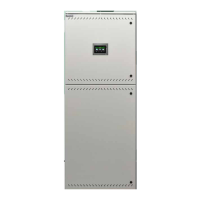
Overview of central battery systems CPS 220/64, CPS 220/20, and sub-station CPUS 220/64.
Specifications and requirements for stationary lead-acid batteries used with the system.
Technical specifications for various CPUSB models, detailing modules, connections, and dimensions.
Detailed instructions for making electrical connections within the system.
Overview of the system's electrical architecture, including substations and BUS connections.
Instructions for connecting the main power supply (X1) to the system, including single and 3-phase configurations.
Connection details for the IB2 device bus (X2) for external components.
Instructions for connecting the optional IB3 device bus (X2) for specific modules.
Connection terminals for additional modules like RIF5, LSA8.1, and DPÜ on terminal rail X8.
Connecting luminaires to the final circuits on terminal rail X3.
Connecting 24V INOTEC LEDs to the final circuits on terminal rail X5.
Procedure for connecting the battery wires to the fuses, ensuring correct polarity.
Instructions for replacing circuit modules in Joker technology, emphasizing voltage-free state.
Warning about replacing circuit modules only when the system is de-energized.
Procedure for assigning a unique address to BUS sub stations via the address switch.
Description of the RIF 5 module for signalling contacts and remote switching.
Proper installation of the Zener terminal for loop monitoring on the last three-phase monitoring module in series to the switching contact.
Description and status indication of the BCS sensor, including LEDs and addressing.
Overview of the BCS module's LCD display, buttons, and functions.
Description and connection details for the LSA 3.1 module.
Activating the integrated DPÜ/B function on the LSA 8.1 module via microswitch.
Monitoring mains voltage at sub-distribution boards using DPÜ/B.2 modules.
Loop monitoring module for detecting short circuits and line interruptions in safety lighting circuits.
Guide to operating the INOWeb interface for monitoring system status and luminaires.
Wiring instructions for using the current loop for local switching of a BUS substation.
Procedure for checking all connections, including BUS, data lines, and external assemblies.
Instructions for performing insulation measurements on final circuits according to VDE 0100.
Step 1: Switch on the mains power supply.
Step 2: Switch on the charger unit.
Step 3: Insert the battery fuses after all other connections are made.
Step 1: Block the system to prevent accidental activation.
Step 2: Remove the battery fuses before disconnecting power.
Step 3: Switch off the mains power supply.
Icon for the Battery Management System (BCS) monitoring battery blocks.
Overview of the main menu structure and its different sections on the TFT controller.
Explanation of the status display indicating the system's operational status.
Explanation of the function buttons used to access different menu areas.
Division of function buttons into luminaire, battery, and component sections.
Accessing the BUS level menu to view change-over devices and final circuits.
Submenu displaying status information for individual luminaires, including destination and operation mode.
Accessing detailed data for the battery, BCS system, and shunt.
Accessing detailed information about the BCS system and individual battery blocks.
Accessing the SLÜ menu for current loop and remote switch configuration.
Simultaneous switching of mains and emergency luminaires using LSA8/LSA 3.1 modules.
Installation of DPÜ/B modules in sub-distribution boards for monitoring general lighting supply voltage.
Opening the main menu by activating the menu button.
Procedure for blocking the device, preventing operation.
Procedure for confirming a manual reset after power failure.
Procedure to deactivate deep discharge protection after it has been activated.
Procedure to manually restart the charging process.
Procedure for saving the current system configuration to a USB flash memory.
Procedure for updating the controller software using a USB flash drive.
Procedure for learning reference values for final circuits with circuit monitoring (SKÜ).
Procedure for automatic detection of luminaires in individual luminaire monitoring (SV).
Methods for programming the system via USB, LAN, or INOTEC Konfigurator software.
Information on how to download and use the INOTEC Konfigurator software.
Detailed steps for configuring the TFT touch controller's network settings for PC communication.
Steps to configure network settings on a Windows 7 PC for communication with the controller.
Accessing the 'Properties' window to set IP address and subnet mask.
Enabling IP address configuration by selecting 'Use following IP address'.
Programming luminaires and change-over devices directly through the TFT Touch controller.
Password protection for programming to prevent unauthorized configuration changes.
Programming luminaires by selecting the circuit and navigating to the luminaire level.
Defining events that trigger automated email notifications from the system.
Specifying the SMTP server IP address or name for email configuration.
Enabling or disabling TLS/SSL encryption for secure data transfer.
Configuring the TLS port number for secure email communication.
Entering the sender's email address for outgoing notifications.
Specifying the POP3 server IP address or name for receiving emails.
Entering the login user name for email access.
Setting a new login password, recommended to avoid special characters.
Procedures for regular inspection and monitoring of batteries and operating devices.
Pre-contact checks for customer service when a failure occurs, including checking luminaire failures.
Steps to check for luminaire failures via the controller's menu.
Procedure to start a function test from the controller's menu.
Action to take if luminaire failures are present: replace illuminants and perform a function test.
Procedure for checking final circuits in case of an insulation error.
Contacting the local agent if failures persist, providing necessary information.
System for monitoring and logging battery block voltage and temperature using BCS sensors.
Test to check if the battery meets the rated operating time, disconnecting automatically upon deep discharge detection.