Do you have a question about the InoTec CPS 220/64 and is the answer not in the manual?
Explains symbols used in the manual for safety and information.
Details INOTEC's responsibility and warranty exclusions for damage.
Specifies that only original INOTEC spare parts must be used for replacements.
Guidelines for the disposal of batteries and electronic components.
Procedure to reset faults by performing a function test after correcting a fault.
Emphasizes reading the mounting and operating instructions for safety and proper use.
States that repairs must only be carried out by INOTEC authorized personnel.
Instructions to check the device for completeness and damage upon receipt.
Guidelines for storing the device and batteries, emphasizing dry and dust-free conditions.
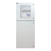
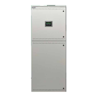
Overview of central battery devices CPS 220/64 and CPS 220/20, main components of the system.
Illustrates the internal structure and connections of the CPUSB 220/64/1-2x2.5A/24V.
Technical specifications for CPS 220/64, CPS 220/20, and CPUS 220/64 devices.
Guidelines for component storage until assembly and installation of the device.
Instructions for placing electronics and battery cabinets on top of each other and connecting them.
Steps for removing the housing hood and attaching the earth wire to the rear wall.
Explains how to expand the CPS 220/64 system with sub stations (CPUS) and BUS sub stations (CPUSB).
Instructions for connecting the power supply system to fuse 1F1 and terminals N, PE.
Connecting external BUS-compatible components via terminals +Bus, ⊥, +24 V on terminal rail X2.
Connecting sub stations or external monitoring systems via terminals R, T, G on terminal rail X2.
Connecting supply voltage from CPS/CPUS to terminals L+, N-, PE; communication via B+ and ^ terminals.
RIF 5 module provides volt-free signalling contacts, remote switching circuit, and monitors main distribution board and battery.
Monitors mains voltage in sub-distribution boards, switches contact on phase failure to interrupt 24V current loop.
Check BUS, data lines, external assemblies, and 24V current loop connections for correct installation and polarity.
Perform insulation measurement on final circuits on terminal block X3 before commissioning.
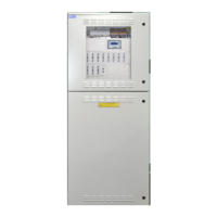
Overview of the CPS 220 controller with a 4-line display, LEDs, and navigation buttons.
Device switches to battery operation to check luminaire functionality and stores results in logbook.
Device operates in battery mode to determine maximum runtime before deep discharge.
Allows system to automatically learn connected luminaires for individual luminaire monitoring (SV).
Displays information about device settings, current faults, and logbook.
Command to delete all logbook entries; data cannot be restored.
Displays the last logbook entry with date and time; allows scrolling through entries.
Allows printing all or a section of the logbook.
Sets the date and time for the controller.
Allows setting a defined time for automatic function tests at 1-63 day intervals.
Loads new configuration data from INOSTICK, overwriting existing data.
Saves current configuration to INOSTICK after entering a file name.
Configures charger count, battery capacity, and shunt size.
Allows programming of the controller, including sub station settings and relay functions.
Tests required after installation according to EN 1838, EN 50172, VDE standards.
Tests must be performed according to national guidelines and recorded in the log book.
Lists information included on the documentation CD in various file formats.
Specifies maximum wire lengths for different connections, considering voltage drop.
Steps to check for luminaire failures, including replacing bulbs and performing function tests.
Procedure for checking final circuits in case of an insulation error.
Contact agent with project name, device type/number, failure description, and controller text.
| Manufacturer | InoTec |
|---|---|
| Model | CPS 220/64 |
| Category | Controller |
| Output current | 64 A |
| Power | 1536 W |
| Protection class | IP20 |
| Output voltage | 24 VDC |