Do you have a question about the InoTec CPS 220 Series and is the answer not in the manual?
Explains safety and information symbols used in the manual.
Outlines INOTEC's warranty limitations and responsibilities.
Specifies requirements for using original INOTEC spare parts.
Provides guidance on the proper disposal of batteries and electronic components.
Describes the need to run a function test after correcting faults.
Emphasizes reading the manual for safe operation and device protection.
States that only authorized personnel can perform repairs.
Instructs to check for completeness and damage upon delivery.
Provides guidelines for storing the device and batteries.
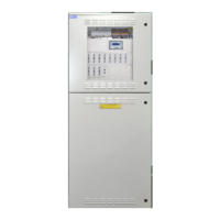
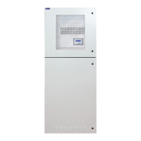
Describes the main components and modular expansion capabilities of the central battery system.
Illustrates the internal layout and component placement of CPS 220/48.1 models.
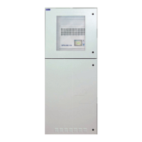
Details the features and expansion levels of CPUSB bus sub-stations.
Lists technical specifications, dimensions, and electrical data for CPS and CPUS devices.
Lists technical specifications, dimensions, and electrical data for CPUSB devices.
Provides instructions for mounting the device, including wall fastening.
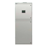
Details the connection of electronics and battery cabinets and cable routing.
Instructions for checking, inserting, and connecting batteries.
Wiring diagram for a single battery cabinet with one battery string.
Wiring diagram for two battery cabinets with one battery string each.
Wiring diagram for two battery cabinets with two battery strings each.
Refers to separate documentation for battery rack mounting.
Refers to documentation CD for battery arrangement in 2000mm cabinets.
Details the electrical connections and system structure.
Shows a system structure diagram connecting various components.
Instructions for connecting the power supply (1-phase and 3-phase).
Details connecting external BUS-compatible components to terminal rail X2.
Explains connecting sub-stations or external monitoring systems to terminal rail X2.
Lists terminals for RIF5, LSA8.1, and DPÜ devices.
Describes connecting luminaires to terminal strips X3, X4, X5.
Outlines the process for connecting battery wires to fuses and terminals.
Explains the types of change-over devices and their programming.
Details the LEDs on change-over devices and connection terminals for CPUSB 220/48.1/6.
Explains wiring the supply voltage for the BUS sub station.
Explains wiring the battery voltage for the BUS sub station.
Describes communication between the main controller and sub stations via device bus IB2.
Explains connecting final circuits to the BUS sub station.
Details assigning unique addresses to BUS sub stations for circuit addressing.
Introduces optional components that enhance system functionality.
Describes the RIF 5 module's functionality and connections.
Details RIF 5 monitoring and optional functions.
Explains RIF 5 signalling contact statuses and remote switching.
Shows RIF 5 wiring diagrams and technical data for UV 1/UV 2.
Describes the BCS battery management system and its requirements.
Details the BCS sensor's LEDs, status indications, and technical data.
Explains the BCS module's display, buttons, and fault indications.
Describes menu navigation (Info, Fault, Programming) for the BCS module.
Explains LSA 3/LSA 8.1 modules for main and safety luminaire control.
Details LSA 3 module connectivity and input channels.
Describes LSA 8.1 modules with inputs and integrated three-phase monitoring.
Explains DPÜ/B activation, selective circuit switching, and sub-db failure message.
Explains DPÜ modules for monitoring sub-distribution board mains voltage.
Details DPÜ features like LED display, phase sequence, and voltage monitoring.
Describes DPÜ/B.2 module for mains voltage monitoring with delay function.
Details DPÜ/B.1 module for mains voltage monitoring and its unit attributes.
Explains LOMO module for monitoring connections for short circuit and loop interruption.
Details the remote mimic panel connection, LEDs, key switch, and technical data.
Describes connecting CPS devices to a central mimic panel via RTG-BUS.
Explains INOWEB module for monitoring CPS device status via a web browser.
Details the PAS for switching to an intact phase during multi-phase failures.
Lists checks for BUS, data lines, external assemblies, and 24V current loop.
Explains performing insulation measurements on final circuits before commissioning.
Details insulation measurement procedures and equipment requirements.
Outlines the correct sequence for powering on the central battery system.
Outlines the correct sequence for powering off the central battery system.
Describes the controller's 4-line display, status LEDs, and current values.
Explains how to access and perform various tests via the controller menu.
Details how to initiate and interpret a function test for luminaire operation.
Explains how to start a battery duration test to check battery runtime.
Introduces the learn mode for automatic luminaire learning.
Guides on using learn mode for individual luminaire monitoring circuits.
Details using learn mode for circuit monitoring circuits.
Explains how to check the deep discharge protection measuring device.
Details checking the insulation monitoring device as per VDE 0108.
Describes how to cancel a running function test and its implications.
Explains how to manually stop an accidentally started battery duration test.
Introduces the info menu for accessing device settings, faults, and logbook.
Guides on accessing information about circuits, charging circuits, and controllers.
Details how to retrieve information for circuits IB1 and IB2.
Provides information on battery duration tests, charger program, and battery capacity.
Guides on retrieving controller information like software version and device settings.
Explains how to print the system configuration from the controller.
Describes how to view and print current fault information.
Explains the logbook function for storing status changes and test results.
Details how to delete all entries from the logbook.
Guides on viewing logbook entries and detailed information.
Explains how to print logbook entries or specific sections.
Displays information about current loops and sub-distribution board failures.
Introduces the programming menu and password protection.
Guides on setting the date and time for the controller.
Details password protection for device settings and the programming menu structure.
Explains how to set automatic test times for function and battery duration tests.
Guides on configuring automatic function tests at set intervals.
Explains how to configure automatic battery duration tests annually.
Details using INOSTICK for configuring and transferring settings to the CPS device.
Guides on loading configuration files from INOSTICK to the CPS device.
Explains how to save configuration files to INOSTICK.
Explains password protection and the main programming menu structure.
Guides on programming charger settings like capacity and shunt size.
Details programming controller settings, including LSA 8 module registration.
Explains activating current loop monitoring with a zener diode.
Explains activating remote switch monitoring with a zener diode.
Details connecting three-phase monitors to bus IB2 and displaying phase failures.
Explains programming the controller as a "device" or "sub station".
Describes manual reset functionality after power failure.
Explains setting the delay for emergency lighting after mains return.
Details blocking operating modes like maintained or emergency lighting.
Explains adjusting the switching time between AC and DC modes.
Guides on setting a 4-digit password for programming protection.
Explains entering destination text for batteries and devices.
Explains how to print the device configuration via printer or INOPRINT.
Guides on selecting slots and programming circuits on the device bus.
Explains assigning up to three input switches (LSA 8, LSA 3, DPÜ/B) to circuits.
Details setting deviation from reference value for circuit monitoring.
Guides on registering and specifying occupancy for up to 20 luminaires per address.
Explains how to delete destination texts for circuits and luminaires.
Guides on accessing the CPS device via IP address and using the web interface functions.
Explains how to view and print device failures from the web interface.
Explains how to access network files and configure links for circuits.
Details entering external links via configurator software or web address.
Explains how to set up a web server for accessing local files and network addresses.
Guides on configuring INOWeb for sending email notifications about system events.
Details setting up project, destination, web password, and email events.
Explains configuring sender/recipient email addresses, POP3 server, and login credentials.
Lists standards for initial testing of the emergency light system.
Emphasizes recording test results and highlights battery limitations after duration tests.
Details daily visual inspection requirements for system readiness.
Explains the weekly test procedure including changeover and luminaire function checks.
Guides on monthly checks, simulating power failure and verifying luminaire function.
Refers to checking insulation monitoring systems.
Outlines annual tests, including battery duration test and charger check.
States the requirement for measuring illumination levels every three years.
Details regular checks for battery and device functionality as per EN 50272-2.
Emphasizes documenting test results in logbooks and retaining them for 4 years.
Lists essential information required for annual battery maintenance records.
Lists information available on the documentation CD, including material lists and wiring diagrams.
Specifies maximum permissible wire lengths for various connections and their cross-sections.
Instructs to check luminaire function and replace illuminants if necessary.
Explains performing a function test after replacing illuminants for luminaire failures.
Directs to check final circuits in case of an insulation error.
Guides on providing information to customer service if failures persist.
| Category | Controller |
|---|---|
| Input Voltage | 24 V DC |
| Output Current | 20 A |
| Number of Outputs | 2 |
| Protection Class | IP20 |
| Storage Temperature | -20°C to +70°C |
| Series | CPS 220 |