51
CPS 220/48.1/SV Montage- und Betriebsanleitung
CPS 220/48.1/SV Mounting and Operating Instructions
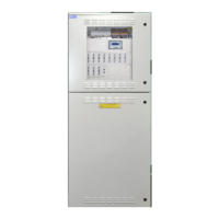
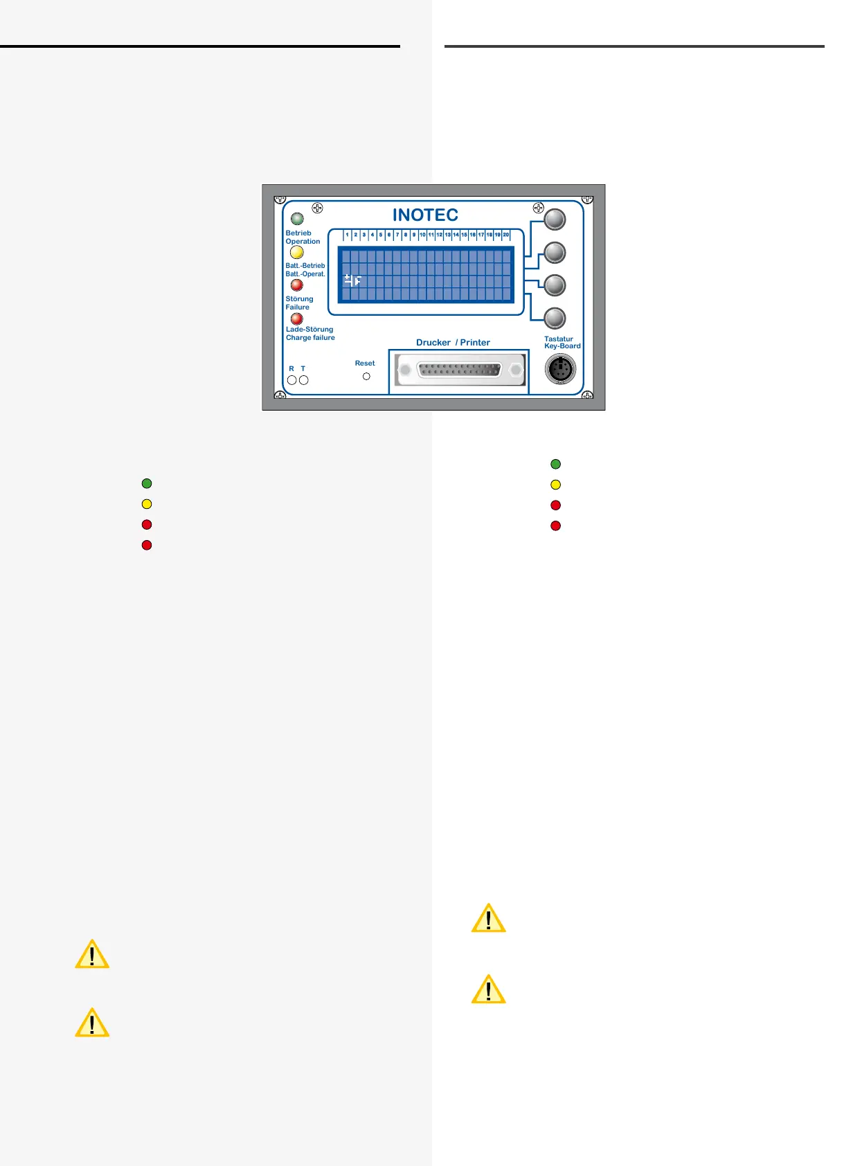
8. 4-zeiliges Steuerteil
8.1. Allgemeines
Das Steuerteil der CPS 220 besteht aus einem 4-zeiligen
Display mit je 20 Zeichen.
Der Zustand der Anlage wird durch 4 Leuchtdioden
aufder linken Seite signalisiert:
(von oben nach unten)
• LED grün
Betrieb
• LED gelb
Batteriebetrieb
• LED rot
Störung
• LED rot
Ladestörung
Bevor das System in den Normalbetrieb umschaltet, zeigt
das Display nach dem Einschalten der Versorgungsspan-
nung zunächst die Softwareversion desSteuerteils an und
initialisiert das System.
Im Normalbetrieb zeigt das Display folgende aktuellen
Werte an:
• Batteriespannung
• Batteriestrom
• Datum
• Uhrzeit
Mit den 4 Tasten auf der rechten Seite können die im Dis-
play angezeigten Funktionen / Menüpunkte ausgeführt /
ausgewählt werden.
Erfolgt bei der Programmierung ca. 1 Minute keine
Eingabe, so wird automatisch zum Hauptmenü zurückge-
schaltet.
An der Centronics-Schnittstelle kann ein her-
kömmlicher Nadel- oder Tintenstrahldrucker
angeschlossen werden. Der Einsatz eines Laser-
druckers ist nicht möglich.
Es können nur Drucker mit Schutzklasse II einge-
setzt werden!
Eine externe Tastatur zur Zielortbearbeitung (z.B. Leuch-
tenzielorte) kann über die PS2-Schnittstelle angeschlos-
sen werden.
Betrieb
Operation
Batt.-Betrieb
Batt.-Operat.
Störung
Failure
Lade-Störung
Charge failure
INOTEC
Drucker / Printer
Reset
R T
Tastatur
Key-Board
1 2 3 4 5 6 7 8 9 10 11 12 13 14 15 16 17 18 19 20
CPS
Betrieb
U=250V I=0,0A
27-01 10:13 Menue
8. 4-line controller
8.1. General
The CPS 220 controller comprises a 4-line display and
each line has 20 characters.
The system status is indicated by 4 LEDs on the left side:
(top to bottom)
• Green LED
Operation
• Yellow LED
Battery operation
• Red LED
Failure
• Red LED
Charging failure
Before the system is switched to standard operation after
the power supply is switched on, the display rst shows
the software version of the controller and initialises the
system.
In standard operation, the display shows the following
current values:
• Battery voltage
• Battery current
• Date
• Time
You can use the 4 keys on the right-hand side to run/se-
lect the functions/menu options shown in the display.
If during programming, approx. 1 minute lapses without
input, you will automatically be returned to the main
menu.
A conventional dot matrix or ink jet printer can
beconnected to the Centronics interface. Use of a
laser printer is not possible.
Only protection class II printers can be used!
An external keyboard for destination processing (e.g.
luminaire destination) can be connected via the PS2inter-
face.
 Loading...