‑14‑
Model
Display
Screen Size
(in inch)
Outline
Dimensions
W x H x D
(mm)
Through‑Hole
Mounting
Dimensions
W × H
(mm)
Mounting‑
Hole
Dimensions
(W+2)
(mm)
Mounting‑
Hole
Dimensions
(H+2)
(mm)
IT7070E‑
BG1
7 200 x 146 x 35 191 x 137 193 139
IT7100E‑
BG1
10.1 271 x 213 x 36 258 x 200 260 202
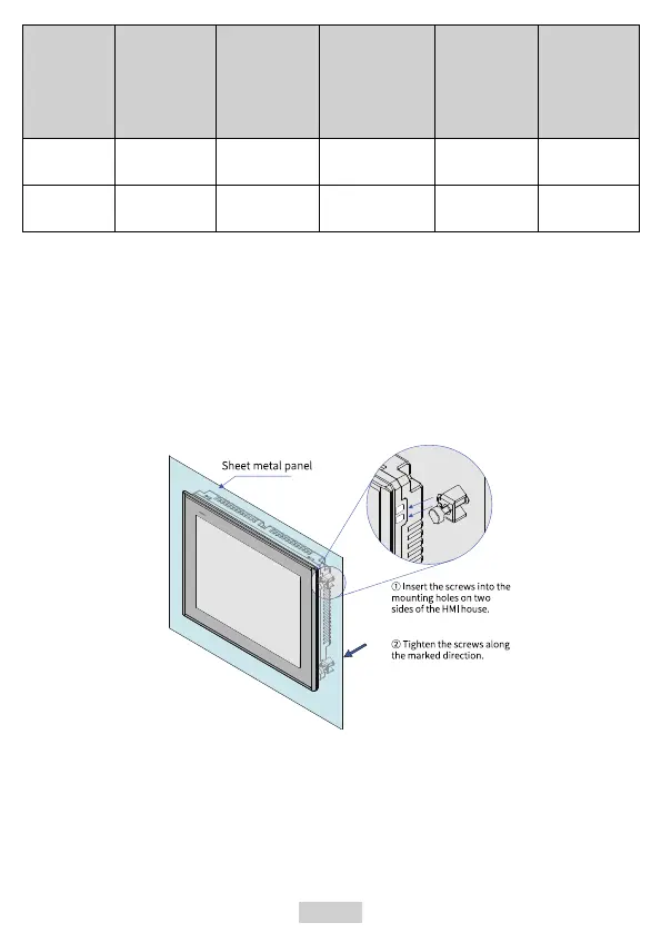
2.3 Installation Mode
When the through hole mounting mode is adopted, install the HMI according to the
following steps.
1. Put the HMI into the pre‑drilled mounting hole in the panel.
2. Snap the four mounting screws (delivered by default) from the back of the panel
into the four mounting holes on both sides of the enclosure (step ① in figure
below).
3. Tighten the mounting screws one by one until the HMI is secured to the panel (step
② in the figure). Recommended torque: 6.0±0.5 kgfcm (to ensure water resistance
and prevent deformation).
 Loading...