Inovance MDBUN Series Braking Unit User Manual
DO is sent as the running/stop signal to the slave. When the master starts braking, DO is
valid; when the master stops braking, DO is cancelled.
2. Slave braking unit
DI is used as start/stop signal input. The slave starts braking when DI is valid and stops
braking when DI is cancelled. When the slave starts braking, DO is valid; when the slave
stops braking, DO is cancelled.
3. TA/TB/ TC
TA and TB are in NC contact, and TA and TC are in NO contact. The three terminals are
used as fault output.
Note that the TA, TB, and TC terminals use the following relay contact specifications. Pay
attention to the control power of the control coil in the main circuit contactor.
NC: 3 A, 250 VAC/1 A, 30 VDC
NO: 5 A, 250 VAC/3 A, 30 VDC
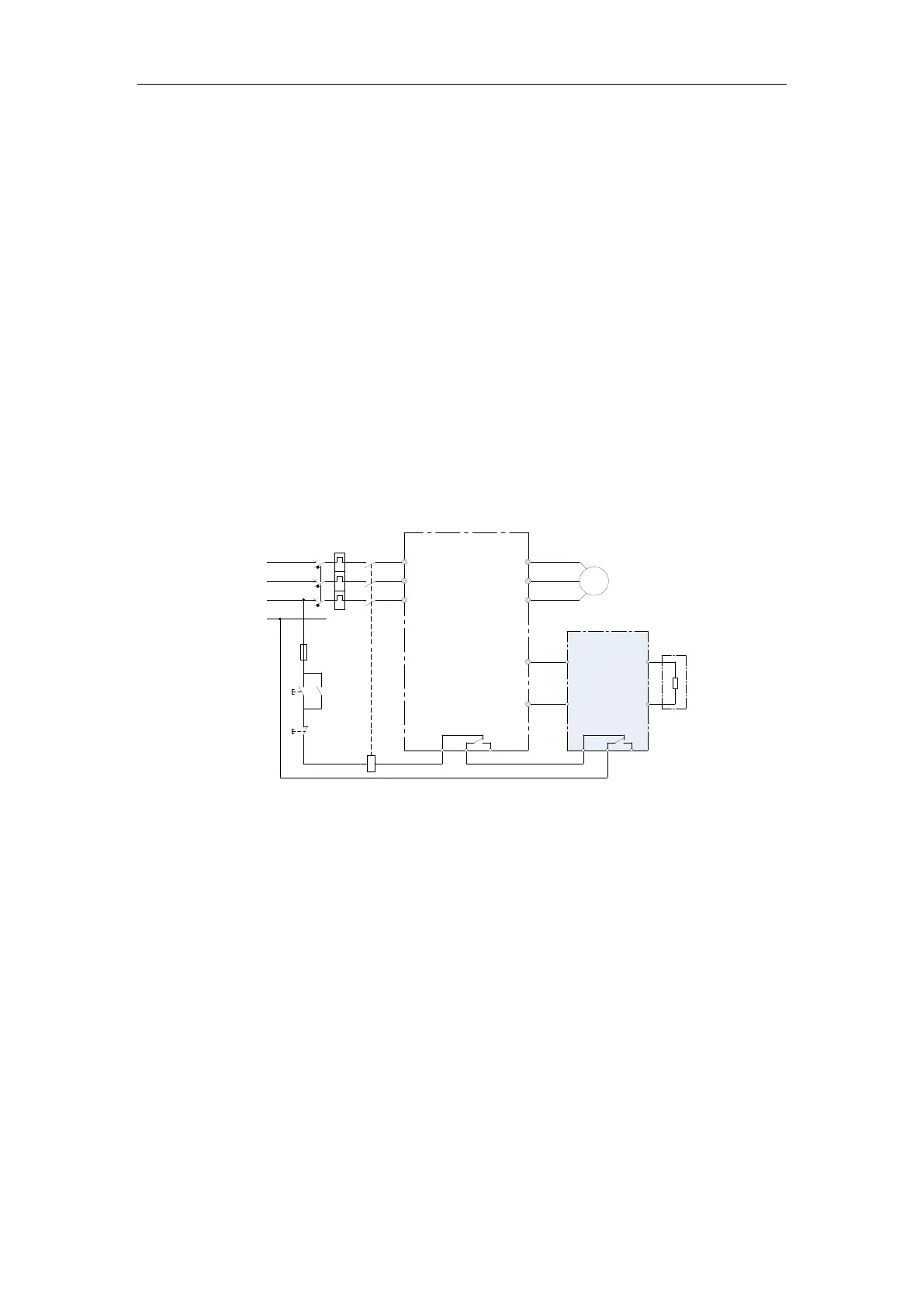
3.2.2 Wiring of the Braking Unit
1. Standard wiring method 1
Figure 3-5 Standard wiring method 1
P
MDBUN
braking
unit
-
+
P(+)
BR
Braking
resistor
Contactor
TB TA TC TB
TA
TC
A2
A1
Circuit
breaker
Inovance
M
Drive
Power
supply
S
R
T
V
U
W
N
N
R
S
T
KM1
FU1
KM1
SA1
start
button
SA2
emergency
stop button
In the preceding wiring method, TA/TB/TC on the drive side are used as relay fault output
of the drive, and TA/TB/TC on the braking unit side are used as relay fault output of the
braking unit.
The input voltage class of the contactor control coil is 220 VAC.
2. Standard wiring method 2
 Loading...