Do you have a question about the Inovance NICE-D-A-S0P2 and is the answer not in the manual?
Details compliance with various certification marks and directives, indicating product standards.
Covers critical safety guidelines, including installation, operation, and maintenance to prevent hazards.
Details essential precautions for motor handling, electrical connections, and environmental factors for safe use.
Explains model naming, nameplate details, physical structure, models, and general specifications.
Outlines environmental conditions, installation location, altitude, temperature, humidity, and vibration for proper setup.
Covers installation environment, dimensions, clearance, and mounting orientation for the controller.
Details main/control circuit wiring, terminal descriptions, and selection of peripheral electrical devices.
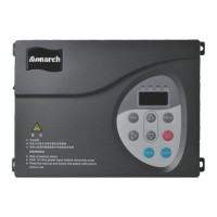
Covers the operation panel layout, key functions, and the three-level menu for parameter management.
Details command sources, motor auto-tuning, speed control, distance control, and door width auto-tuning.
Explains running curves for different modes and how to handle 'door close hindered' situations.
Explains the structure, meaning of columns, and symbols used in the function code tables.
Details basic parameters (F0) and motor parameters (F1) for controller and motor configuration.
Covers performance control (F2) and running curve parameters (F3, F4) for door open/close operations.
Details auxiliary (F5, F8), distance control (F6), demonstration (F7), and I/O (F9) parameters.
Covers display/fault (FA) and user (FP) parameters for monitoring, diagnostics, and security.
Details F0 basic parameters (control, command source) and F1 motor parameters (type, ratings, auto-tuning).
Explains F2 performance control, F3 door open, and F4 door close running curve parameters.
Covers F5 auxiliary, F6 distance control, F7 demonstration, F8 auxiliary, and F9 I/O parameters.
Details FA display/fault parameters and FP user parameters like password and update functions.
Outlines routine maintenance, periodic inspection, cleaning, and replacement of vulnerable components.
Provides a comprehensive guide to fault codes, their causes, and effective troubleshooting steps.
| Category | Door Opening System |
|---|---|
| Model | NICE-D-A-S0P2 |
| Input Voltage | 24V DC |
| Output Current | 2A |
| Protection Level | IP20 |
| Storage Temperature | -20°C to +70°C |
| Humidity | 5% to 95% non-condensing |