© Inovonics, 2011 - www.inovonics.com
EN4204/R EchoStream
®
Receiver
Installation Instructions - 05617C
1 Quick Start
By following this procedure you can quickly configure receiver. Review the
main body of this manual for additional options, features, and a more
detailed startup process.
1. Open the receiver housing.
2. Connect the power cabling.
3. Set the frequency band.
4. Press the Advance button to select the first transmitte
r point to
pr
ogram.
5. Press the Program button to begin programming the point.
6. Use the Advance button to choose a supervision windo
w; press
Program to
complete and advance to the output option.
7. Use the Advance button to select the output number; press Program
to complete and advance to the output type option.
8. Use the Advance button to select the output type. If programming
the
EN42
04 press Program to complete and advance to the switch
type
opt
ion; if programming the EN4204R, press Program
to complete and
skip to step 10
.
9. Use the Advance button to choose between nor
mally open and
nor
mally closed; press Program to complete programming.
10. If you wish to register a transmitter to the point you’ve just programmed,
press the transmitter’s Reset button; otherwise, press Program to save
programming changes without registering a transmitter.
11. Press Advance to choose the next transmitter point to program.
Caution: Make sure to press Advance to choose the transmitter point you
want to program. If you press Program instead of Advance, you will
reprogram the first transmitter point.
12. Follow steps 5 through 11 to program the next transmitter point.
13. If programming an EN4204, press Advance to choose the fault ouput; if
programming an EN4204R skip to step 15.
Note: The EN404R fault outputs can be wired normally open or normally
closed using the terminal blocks.
14. Use the Advance button to choose between between normally o
pen
and
normally closed; press Program to complete programming.
15. Connect input and output cabling.
16. Mount the receiver.
2 Overview
The EN4204/R receiver allows you to add up to four transmitters to any
application. With diversity reception and advanced signal processing,
Inovonics Wireless EchoStream technology is designed to minimize dead
spots in transmission areas.
2.1 Inovonics Wireless Contact Information
If you have any problems with this procedure, contact Inovonics Wireless
technical services:
• E-mail: support@inovonics.com
• Phone: (800) 782-2709; (303) 939-9336
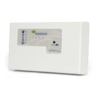
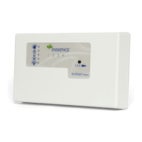
2.2 EN4204/R LEDs and Buttons
Figure 1 Receiver LEDs and Buttons
Most of the LEDs and buttons perform different function depending on
which mode the the EN4204/R is in.
Normal Operation Mode
Alarm LED: Lights when any transmitter is sending an alarm transmission.
Tamper Fault LED: Lights when any transmitter is sending a tamper
transmission.
Low Battery Fault LED: Lit when any transmitter has a low battery.
Inactive Fault LED: Lit when any transmitter is inactive.
Power LED: Lit when receiving power.
Transmitter Number LEDs: Lit when the transmitter is in alarm.
Advance Button: Press the Advance button to enter status review mode.
Decode LED: Flashes when any recognizable transmission is received.
This LED is only visible when the pry-out door or cover is removed.
Reset Button: Clears the current status for all points and resets all outputs
and LEDs. Resets the supervision window timers. This button is only
accessible when the pry-out door or cover is removed.
Status Review Mode
Alarm LED: Lights when the selected transmitter is sending an alarm
transmission.
Tamper Fault LED: Lights when the selected transmitter is sending a
tamper transmission.
Low Battery Fault LED: Lit when the selected transmitter has a low
battery.
Inactive Fault LED: Lit when the selected transmitter is inactive.
Power LED: Lit when receiving power.
Transmitter Number LEDs: Shows status of the transmitter assigned to
that number when lit. Use the advance button to scroll through transmitters.
Advance Button: Scrolls through transmitters to display status.
Decode LED: Flashes when any recognizable transmission is received.
This LED is only visible when the pry-out door or cover is removed.
Reset Button: Clears the current status for all points and resets all outputs
and LEDs. Resets the supervision window timers. This button is only
accessible when the pry-out door or cover is removed.
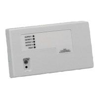
2.3 EN4204 Internal Components
Figure 2 EN4204 Components
A Alarm LED B Tamper Fault LED C Low Battery Fault LED
D Inactive Fault LED E Power LED F Transmitter Number LEDs
G Advance Button H Decode LED I Reset Button
A Housing release
tabs
B Power (11-14
VDC)
C Ground connection
D Output terminals E Fault output F Advance button
G Reset button H Reset input I Jam output
J Tamper output K Program button L Frequency band selection
pins
M Decode LED
Click Here