EasyManua.ls Logo

Inovonics EN4232MR User Manual

Inovonics EN4232MR
6 pages
To Next Page IconTo Next Page
Page #1 background imageLoading...
Page #1 background image
2/3/20 357-05819-02 Rev A © Inovonics, 2020 - www.inovonics.com
EN4232MR 32 Zone Multi-Condition
Receiver with Relay Outputs
Installation and Operation Manual
1 Overview
The EN4232MR receiver allows you to add up to 32 transmitters and 11
outputs to any application, and includes a back tamper for increased
tamper security.
Inovonics add-on receivers use Form C relays to allow connection to any
hardwired panel or stand-alone wireless application.
The following add-on receivers are available from Inovonics:
* At least one relay must be used for faults to ensure the system is
supervised. More than one relay may be used, but that will deduct from the
number of alarm output relays.
1.1 Installing an Inovonics Security System
An EchoStream survey kit must be used to establish a UL system. The
EchoStream survey kit measures the signal strength of high-power
repeater and sensor messages to help optimize your EchoStream system.
Figure 1 Sample EchoStream system
The EchoStream survey kit provides you with two signal strength
measurements: signal level and signal margin.
Signal level: The signal level is the measurement of the overall decibel
level of the message.
Signal margin: The signal margin is the measurement of the decibel level of
the message, minus the decibel level of any interfering signals. Inovonics
Wireless equipment should be placed within a facility such that all end-
devices produce signal margin readings of at least 4 decibels.
Both the signal level and signal margin are measured in decibels. Because
signal strength and signal margin are measured on a logarithmic scale, the
difference between a decibel level of 3 (Weak) and a decibel level of 4
(Good) is a much larger difference than it would be on a linear scale.
Note: For more information about the EchoStream survey kit, see the
EN7017 Survey Kit and App Installation and Site Survey Instructions.
Caution: The EchoStream system should be tested regularly to ensure
operation. To test: place the system in test mode, activate an end device,
and ensure an appropriate response.
1.2 RF Signal Propagation
While wood, drywall and glass usually let the RF signals pass, some
materials may inhibit or attenuate radio frequency (RF) signal propagation
by blocking, reflecting, deflecting or absorbing RF signals.
Consider anything between transmitters and repeaters and/or the receiver.
Is there concrete and steel construction? Are there earthen berms or hills?
Are there a lot of trees? Devices should be mounted such that they are
least affected by these elements.
For best results, transmitters and repeaters should be mounted at the
optimal height to achieve line of sight to repeaters and/or the receiver.
Usually this means they will be mounted as high as possible.
Following are some typical obstacles to RF signal propagation:
1.3 Inovonics Contact Information
Receiver
Alarm Output
Relays
Fault Relays
Transmitters
Supported
EN4204R 4 1 4
EN4216MR 5 1* 16
EN4232MR 11 1* 32
Material Affect Recommendation
Metal construction,
including ductwork;
pipes; studs; stucco,
plaster or concrete with
wire mesh; satellite
dishes, metal-lined
rooms such as walk-in
coolers or freezers;
metal siding, safes, etc.
Can reflect,
absorb and/or
disrupt RF
signals.
Perform a site survey
using an Inovonics
wireless survey kit to
verify the RF signal is
acceptable, and, when
necessary, to
determine where to
locate repeaters.
Completely enclosed
metal boxes/enclosures.
Can restrict RF
signals.
Solar panels, cinder
block walls, windows
with built-in solar tinting.
Can absorb and/
or reflect RF
signals.
Vegetation. Can attenuate
RF signals. The
RF environment
can alter as
trees shed or
sprout leaves.
Add repeaters as
issues arise.
Automobile and truck
traffic.
Can disrupt RF
signals.
Mount Inovonics
devices at a height
sufficient to achieve
line of sight above
traffic.
For product and installation videos visit us at
www.inovonics.com/videos or use the QR
code below.
Question and Answer IconNeed help?

Do you have a question about the Inovonics EN4232MR and is the answer not in the manual?

Inovonics EN4232MR Specifications

General IconGeneral
Frequency Range902-928 MHz
Sensitivity-110dBm
Data Rate19.2 kbps
Protocol SupportInovonics EchoStream
Operating Temperature+60°C
Connectorterminal block
Dimensions6.5 x 5.5 x 1.6 inches

Summary

1 Overview

1.1 Installing an Inovonics Security System

Guidance on using the EchoStream survey kit to measure signal strength for system optimization.

1.2 RF Signal Propagation

Details common obstacles affecting RF signal propagation and recommendations for optimal placement.

2 Installation and Startup

2.1 Installation Notes

Key points for installing Inovonics products, including testing and proximity to control units.

2.2 Power Cabling

Instructions for connecting power to the receiver, including voltage, current, and wire gauge requirements.

2.3 Select the Frequency Band

Guide to setting the receiver's radio frequency band using jumpers for different geographic regions.

2.4 Input/Output Cabling

Details on connecting various input and output terminals for system integration.

2.5 Mount the Receiver

Instructions for physically mounting the receiver, considering RF interference and UL requirements.

3 Point Setup and Registration

3.1 Factory Configuration Defaults

Information on the receiver's pre-programmed output configurations and how to register transmitters.

3.2 Program a Point

Steps to access menus and program individual points for transmitter registration and configuration.

4 32 Zone Multi-Condition Receiver with Relay Outputs Operation and Point Setup Screens

4.1 Menu Tree

Overview of the receiver's menu structure, listing key functions and their respective page references.

4.2 EN4232MR Start Screen

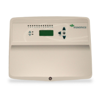
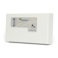
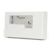
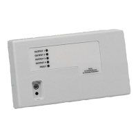
Description of the receiver's main display, showing alarm, fault, and ready status information.

4.3 Point Status

How to view detailed alarm and fault information for each configured point on the receiver.

4.4 Event Log

Accessing and viewing the receiver's event log for historical alarm, fault, and event data.

4.5 Install & Service

Menu for system configuration, maintenance, and troubleshooting.

4.5.1 Setup Point

Detailed steps for configuring individual points, including supervision, security, alarm mapping, and output types.

4.5.2 Register Transmitter

Procedure for registering a transmitter or repeater to a specific point on the receiver.

4.5.3 Delete Point

Instructions for deleting transmitter registration information from points or clearing all registrations.

4.5.4 Signal Strength

Measuring and interpreting signal strength and margin for troubleshooting installation issues.

4.5.5 Change Password

Steps to change the default password for accessing install and service menus.

4.5.6 Factory Config

Procedure to restore the EN4232MR to its original factory default settings.

5 Specifications

6 UL Requirements

7 Television and Radio Interference

8 FCC Part 15 and ISED Compliance

9 Radiation Exposure Limits

9.1 FCC

FCC guidelines on radio frequency exposure limits for the equipment and antenna placement.

9.2 ISED

ISED RSS-102 guidelines on radiation exposure limits for the equipment and antenna placement.

Related product manuals