SMART CHARGE IUoU Chargers
13
Front view 466095 (see figure 2)
The units can charge up to two supply batteries
No. Description
1 Half power mode button
2 Connection for remote control
3 Control lamp
4 Switch field for the selection of the charging voltage
and time limitation (figure 8)
5 “+“ (plus) terminal for the supply battery (1A Charge)
6 “+” (plus) terminal for the supply battery
7 “+” (plus) terminal for the supply battery
8 “-“ (minus) terminal for the supply battery
5 Settings
5.1 Charging voltage and time
A switch field can select the charging voltage and the period for the main
charging phase.
Warning!
Make sure that switch 1 and 2 or switch 3 and 4 are never switched
on simultaneously while operating the charger. Please follow the
table below to ensure correct operation of the charger
5.1.1 Settings for the charging voltage
Refer to figure 8:
Voltage Switch 1 Switch 2 Application range
13.8 V OFF OFF Starter batteries, or using as a
12V power supply
14.4 V ON OFF Lead acid and gel batteries
14.8 V OFF ON AGM batteries
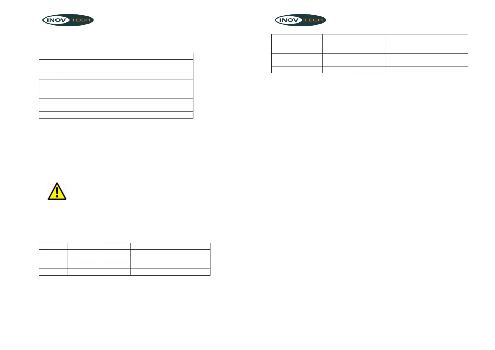
5.1.2 Settings for the limitation of the period of the main charging
phase
Refer to figure 8:
SMART CHARGE IUoU Chargers
14
Time limitation of
the main
charging
Switch 3 Switch 4 Application range phase
4 hrs. OFF ON Lead acid or Starter batteries
8 hrs ON OFF AGM batteries or Gel batteries
No timer function OFF OFF Using as a 12V power supply
5.2 Half power mode
If you push the button “Half Power Mode”, the output power will reduce to half
the chargers amp rating and a green “Half ON” LED will light. The Half Power
LED is located on the bottom left corner of the front panel.
6 Mounting of Battery Charger
For the mounting of battery charger on wall or flat places, please refer to figures
10 & 11 regarding size of housing and location of mounting holes for your
installation.
7 Making Connections
o Place the charger in a dry, cool, clean, and ventilated space.
o Set the power switch to “0” (off) and pull out the main plug before
connection or disconnecting the direct current connection.
o Connect the “-“(minus) battery pole with a connecting cable to
the”-“(minus) terminal at the IU0U automatic charger (see figure 1 & 2).
o Connect the “+”(plus) battery pole with the connecting cable to the
“+”(plus) terminal at the IU0U automatic charger (see figure 1 & 2).
o Lay all the cables from the batteries to the IU0U automatic charger (refer
to figure 6)
o Fasten the cables ends with provided terminals (refer to figure 5).
o For connection of starter batteries, please connect the terminal as our
drawing (see figure figure 7).
o Ensure correct polarity of the battery and the battery charger, otherwise
the internal flat-pin terminal will trigger with the wrong polarity.
Note
Only use cables with the prescribed wire cross sections fro the connection of the
IU0U automatic charger to the battery.