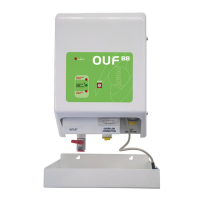
OUF 88 INSTALLATION
Installation must be in accordance with BS 5410 + any
local building regulations
1/ Connect the suction line from the main tank to the ‘inlet’, and
the supply pipe (‘gravity fed’) to the appliance to the outlet.
Connect the overflow facility (*).
If your pipe is in PVC or Copper you are required to use a 10mm
pipe insert at any junction that has a compression fitting.
2/ Connect the GPS 10 to the mains supply either through a
plug (not included) or fused electric spur (see wiring diagram page 5).
The mains supply cable has to pass trough the access hole to
the back part of the mounting plate
Once powered up, low level led & green power light will come on.
3/ To start the OUF automatic operation, press and keep
pressed the start button, which will start the pump, filling the
OUF 88 reservoir, until the Low Level lamp turns off.
The pump may be noisy initially until the fuel starts coming
through to the pump.
Auto fill mode – Please read before powering the unit.
- Switch on 240v power to the unit
- Within 5 seconds press start button and hold in.
- The OUF 88 will display a light sequence.
- The pump will then start running/sucking.
- Release the start button. The unit is now in automatic mode.
- Whilst in automatic mode the lower 2 leds flash intermittently. (see details P10)
Once reached the low level, you can release the start button,
because the OUF works in automatic mode.
4/ Once the oil has filled the OUF 88 reservoir to the
programmed maximum level (80% approx), the working level
switch will stop the pump.
5/ The OUF is now ready for use and the appliance(s) can be
used. The OUF 88 will manage the fuel supply automatically.
(*) The overflow connection is dual purpose:
1) It must be connected with a return pipe to the tank as a safety feature in the
event that the float switch fails. A leak detector & oil tray are available as an
alternative if it is not possible to take the overflow back to the tank. The
manufacturer will refuse any liability for damages at any installation without at
least one these two additional safety options fitted.
2) It can be connected to the oil tank to allow venting of the OUF88 reservoir if it
is required to be sealed to prevent unwanted smells.
OUF 88 with leak detection system. Wiring diagram
Connections above detailed by dashed line, have to be fitted by the
leak detection system installer.
An insulated three wire cable is provided for this purpose.
Note: The is only operational
when the Leak Detector & L.D. Board
are fitted.
8
3


 To Next Page
 Loading...