Original Language - English
GOWIRELESS: The optional GOWIRELESS LRT (Long Range Transmission) system enables wireless use.
The transmitter can be mounted on wrist, hose, belt clip, lanyard, or in pocket.
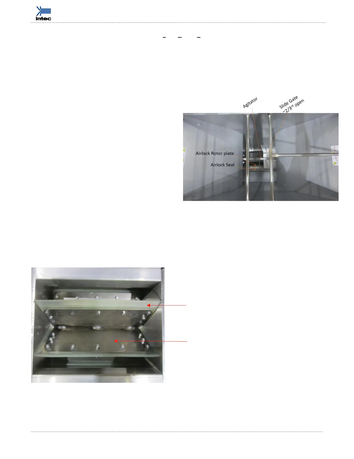
Agitator: The agitator is located in the bottom section of the hopper between the hopper and airlock.
The configuration of the agitator enables high production rates and appropriate insulation
conditioning.
Slide Gate: The slide gate is between the agitator
and the airlock. The slide gate allows the user to
alter the volume of insulation being swept into the
airlock over time. An open slide gate provides the
maximum amount of insulation into the airlock
over time; often this is the case when open blowing
attics. Closing the slide gate provides more
conditioning to the insulation. When the slide gate
restricts insulation flow into the airlock the
insulation comes into more contact with the
agitator, resulting in increased conditioning of the
insulation and more airflow vs. product flow ratio.
The slide gate is typically used during wall fill
applications where the user desired a higher ratio
of air to product flow to pack the insulation densely
into wall cavities.
Airlock: The airlock transfers the insulation from the agitation system into the airstream. Note
insulation does not come into contact with the blower. Insulation is discharged from the airlock by
way of the machine outlet into the hose. Hose is not shown in above diagram; hose is connected to
the Machine Outlet.
Each Blade is welded to the Airlock Shaft for superior strength.