inter
MEMORY INTERFACING
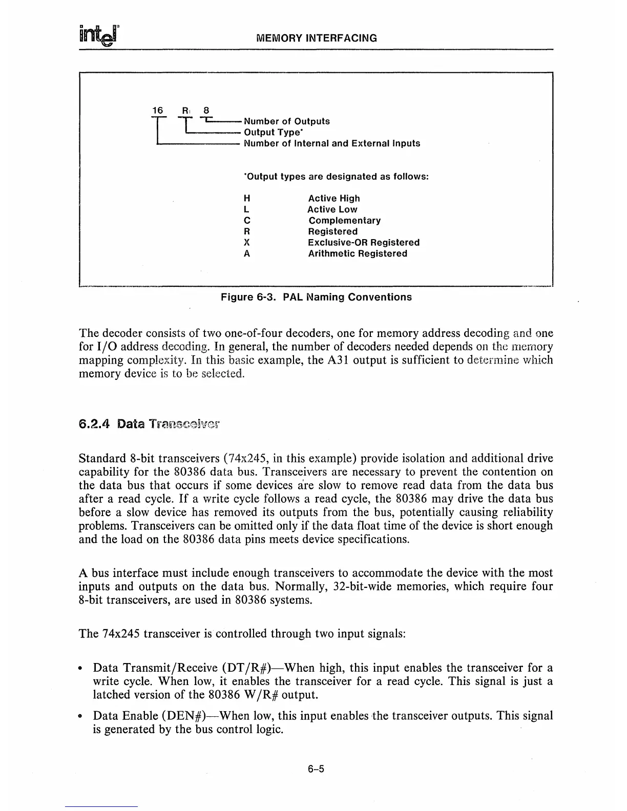
16
RI
8
T
T
L:....-
Number
of
Outputs
'-----
Output
Type'
...
-------
Number
of
Internal
and
External
Inputs
'Output
types
are
designated
as
follows:
H
L
C
R
X
A
Active
High
Active
Low
Complementary
Registered
Exclusive-OR
Registered
Arithmetic
Registered
---_._----------------------------
Figure
6-3, PAL Naming
Conventions
The decoder consists of two one-of-four decoders, one for memory address decoding and one
for
I/O
address decoding. In general, the number of decoders needed depends
on
the memory
mapping complexity. In this basic example, the
A31
output
is
sufficient to determine which
memory device
is
to be selected.
Standard 8-bit transceivers (74x245, in this example) provide isolation and additional drive
capability for the
80386 data bus. Transceivers are necessary to prevent the contention on
the data bus
that
occurs if some devices are
slow
to remove read data from the
data
bus
after a read cycle.
If
a write cycle follows a read cycle, the 80386 may drive the data bus
before a
slow
device has removed its outputs from the bus, potentially causing reliability
problems. Transceivers can be omitted only if the data float time of the device
is
short enough
and the load on the
80386 data pins meets device specifications.
A bus interface must include enough transceivers to accommodate the device with the most
inputs and outputs on the data bus. Normally, 32-bit-wide memories, which require four
8-bit transceivers, are used in
80386 systems.
The 74x245 transceiver
is
controlled through two input signals:
• Data Transmit/Receive (DT
/R#)-When
high, this input enables the transceiver for a
write cycle. When
low,
it enables the transceiver for a read cycle. This signal
is
just a
latched version of the
80386 W
/R#
output.
• Data Enable
(DEN#)-When
low,
this input enables the transceiver outputs, This signal
is
generated by the bus control logic.
6-5