CACHE SUBSYSTEMS
Table
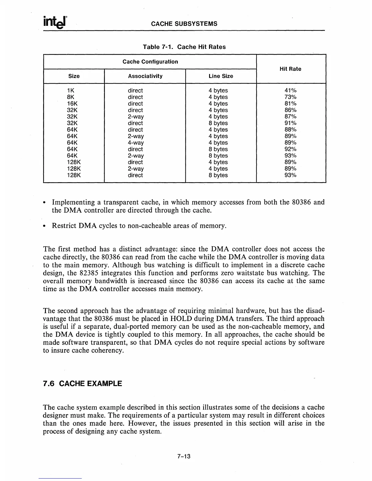
7-1_
Cache Hit Rates
Cache Configuration
Hit Rate
Size Associativity Line Size
1K direct 4 bytes 41%
8K direct 4 bytes
73%
16K direct
4 bytes
81%
32K direct 4 bytes 86%
32K 2-way
4 bytes
87%
32K direct 8 bytes 91%
64K direct 4 bytes 88%
64K
2-way
4 bytes
89%
64K 4-way 4 bytes 89%
64K direct 8 bytes
92%
64K 2-way 8 bytes 93%
128K
direct
4 bytes 89%
128K 2-way 4 bytes 89%
128K direct 8 bytes 93%
• Implementing a transparent cache,
in
which memory accesses from both the 80386 and
the DMA controller are directed through the cache.
• Restrict DMA cycles to non-cacheable areas of memory.
The first method has a distinct advantage: since the DMA controller does not access the
cache directly, the
80386 can read from the cache while the DMA controller
is
moving data
to the main memory. Although bus watching
is
difficult to implement
in
a discrete cache
design, the 82385 integrates this function and performs zero waitstate bus watching. The
overall memory bandwidth
is
increased since the 80386 can access its cache
at
the same
time
as
the DMA controller accesses main memory.
The second approach has the advantage of requiring minimal hardware, but has the
disad-
vantage that the 80386 must be placed
in
HOLD during DMA transfers. The third approach
is
useful if a separate, dual-ported memory can be used
as
the non-cacheable memory, and
the DMA device
is
tightly coupled to this memory. In all approaches, the cache should be
made software transparent,
so
that DMA cycles
do
not require special actions by software
to insure cache coherency.
7.6
CACHE EXAMPLE
The cache system example described in this section illustrates some of the decisions a cache
designer must make. The requirements of a particular system may result
in
different choices
than the ones made here. However, the issues presented
in
this section
will
arise in the
process of designing any cache system.
7-13

 Loading...

