inter
82289AEN#
MUlTIBUS® XACK#
(BUS
CONTROllER)
ENDCYC2
ADSO#
ClK
82288 ALE
MUL
TIBUS®
I AND
80386
]
ARDY
J
J
Q
r--
K
-
i>
rP
WSl
J
Q
K
16R8
-
-
1
>-
-
ClK#
PClK
MBEN
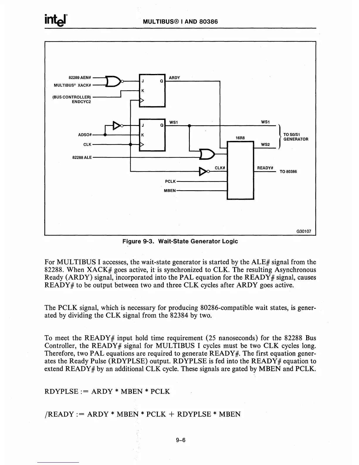
Figure
9-3.
Wait-State
Generator
Logic
WSl
WS2
READY#
I
TO
50/51
GENERATOR
TO
80386
G30107
For MUL TIBUS I accesses, the wait-state generator
is
started
by
the ALE# signal from the
82288. When XACK#
goes
active,
it
is
synchronized to CLK. The resulting Asynchronous
Ready (ARDY) signal, incorporated into the PAL equation for the READY # signal, causes
READY # to be output between
two
and three CLK cycles after ARDY goes active.
The PCLK signal, which
is
necessary for producing 80286-compatible wait states,
is
gener-
ated
by
dividing the CLK signal from the 82384 by
two.
To
meet the READY # input hold time requirement (25 nanoseconds) for the 82288
Bus
Controller, the READY# signal for MULTIBUS I cycles must be
two
CLK cycles long.
Therefore, two PAL equations are required to generate READY
#.
The first equation gener-
ates the Ready Pulse (RDYPLSE) output. RDYPLSE
is
fed
into the READY # equation to
extend READY #
by
an additional CLK cycle. These signals are gated by MBEN and
PCLK
RDYPLSE : = ARDY * MBEN * PCLK
/READY
: = ARDY * MBEN * PCLK + RDYPLSE * MBEN
9-6
 Loading...


