MUL TIBUS® I AND
80386
9.2.4
Bus
Controller and
Bus
Arbiter
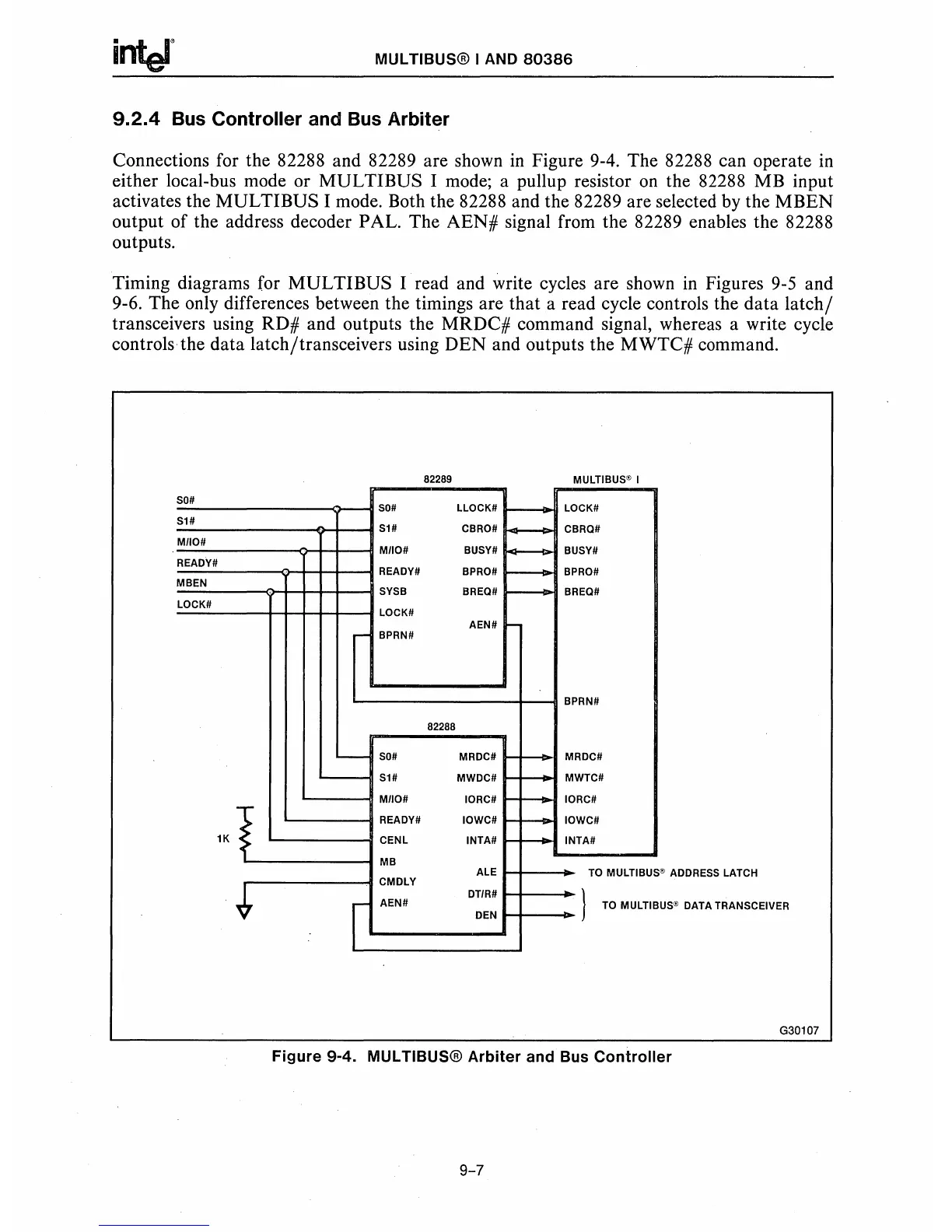
Connections for the 82288 and 82289 are shown
in
Figure 9-4. The 82288 can operate in
either local-bus mode or
MULTIBUS
I mode; a pullup resistor
on
the 82288 MB input
activates the
MULTIBUS
I mode. Both the 82288 and the 82289 are selected by the
MBEN
output of the address decoder PAL. The
AEN#
signal from the 82289 enables the 82288
outputs.
Timing diagrams for
MULTIBUS
I read and write cycles are shown
in
Figures 9-5 and
9-6. The only differences between the timings are that a read cycle controls the
data
latch/
transceivers using RD# and outputs the MRDC# command signal, whereas a write cycle
controls the
data
latch/transceivers using
DEN
and outputs the
MWTC#
command.
82289
MULTIBUS@ I
50#
r---
50#
LLOCK#
LOCK#
51#
51#
CBRO#
-
CBRa#
M/IO#
M/IO#
BUSY#
+--
BUSY#
READY#
READY# BPRO#
-
BPRO#
MBEN
SYSB
BREa#
r------
BREa#
LOCK#
LOCK#
AEN#
-
BPRN#
BPRN#
82288
-
50#
MRDC#
r--
MRDC#
'------
51#
MWDC#
r---
MWTC#
.,..
M/IO# 10RC#
r---
10RC#
~
READY# 10WC#
f--
10WC#
1K
~
CENL
INTA#
r--
INTA#
MB
ALE
TO
MULTIBUS'
~
ADDRESS
LATCH
CMDLY
*
DT/R#
}
I
AEN#
TO
MULTIB
DEN
US~
DATA
TRANSCEIVER
G30107
Figure
9-4. MUL TIBUS®
Arbiter
and
Bus
Controller
9-7
 Loading...


