LOCAL BUS INTERFACE
Bus States:
ALWAYS
READY#
ASSERTED·
REQUEST
PENDING
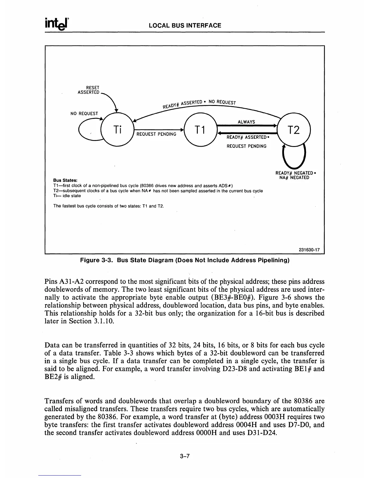
Tl-first
clock of a non-pipe lined
bus
cycle (80386 drives new address
and
asserts
ADS")
T2-subsequent
clocks of a
bus
cycle
when
NA"
has not been sampled asserted
in
the current bus cycle
Ti-
idle state
The fastest bus cycle consists of two states:
Tl
and
T2.
READY#
NEGATED.
NA#
NEGATED
231630-17
Figure
3-3. Bus
State
Diagram
(Does
Not
Include
Address
Pipelining)
Pins A31-A2 correspond to the most significant bits of the physical address; these pins address
doublewords of memory. The two least significant bits of the physical address are used inter-
nally to activate the appropriate
byte enable output (BE3#-BEO#). Figure 3-6 shows the
relationship between physical address, doubleword location, data bus pins, and byte enables.
This relationship holds for a 32-bit bus only; the organization for a 16-bit bus
is
described
later in Section 3.1.1
O.
Data can be transferred
in
quantities of
32
bits,
24
bits,
16
bits, or 8 bits for each bus cycle
of a data transfer. Table
3-3
shows which bytes of a 32-bit doubleword can be transferred
in a single bus cycle.
If
a data transfer can be completed in a single cycle, the transfer
is
said to be aligned. For example, a word transfer involving D23-D8 and activating BE1# and
BE2#
is
aligned.
Transfers of words and doublewords that overlap a doubleword boundary of the
80386 are
called misaligned transfers. These transfers require two bus cycles, which are automatically
generated by the 80386. For example, a word transfer at (byte) address
0003H requires two
byte transfers: the first transfer activates doubleword address
0004H and uses
D7-DO,
and
the second transfer activates doubleword address
OOOOH
and uses D31-D24.
3-7