IDLE
TI
ClK2
[
(82384
ClK)
[
BEO
#-BEI
#
A2-A31.
[
M/IO
#.D/C#
W/R#
[
ADS# [
NA#
[
BS16 # [
READY
# [
lOCK # [
DO-D31[-
LOCAL BUS INTERFACE
I
CYCLE
1 I
NON-PIPElINED
(READ)
T1
T2
T1
CYCLE
2
NON-PIPELINED
(WRITE)
T2 T2
IDLE
I
TI
Tl
CYCLE
3
NON-PIPELINED
(READ)
T2
T2
IDLE
I
n
231630-16
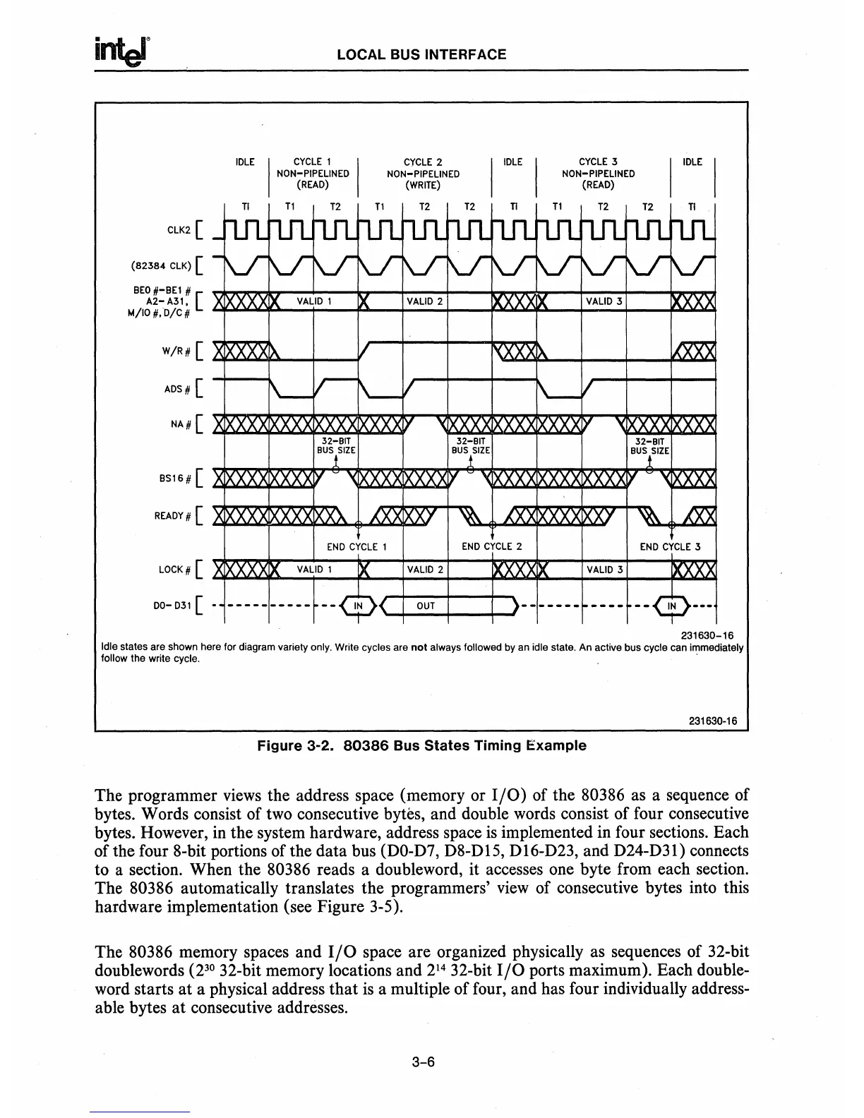
Idle states are shown here for diagram variety only. Write cycles are
not
always followed by an idle state. An active bus cycle can immediately
follow the write cycle. .
231630·16
Figure 3-2.
80386
Bus
States
Timing Example
The programmer views the address space (memory or
I/O)
of the 80386 as a sequence of
bytes. Words consist of two consecutive bytes, and double words consist of four consecutive
bytes. However, in the system hardware, address space
is
implemented in four sections. Each
of the four 8-bit portions of the data bus
(DO-D7, D8-D15, D16-D23, and D24-D31) connects
to a section. When the
80386 reads a doubleword, it accesses one byte from each section.
The
80386 automatically translates the programmers'
view
of consecutive bytes into this
hardware implementation (see Figure 3-5).
The
80386 memory spaces and
I/O
space are organized physically as sequences of 32-bit
doublewords
(2
30
32-bit memory locations and
214
32-bit
I/O
ports maximum). Each double-
word starts
at
a physical address
that
is
a multiple of four, and has four individually address-
able bytes
at
consecutive addresses.
3-6