LOCAL
BUS
INTERFACE
NA'ILl
NA,
(PIN
'13)
I
(INTERNAL)
8516#
8516#)
(PIN
C14)
1 (INTERNAL)
80386
CHIP
..-
-
231630-22
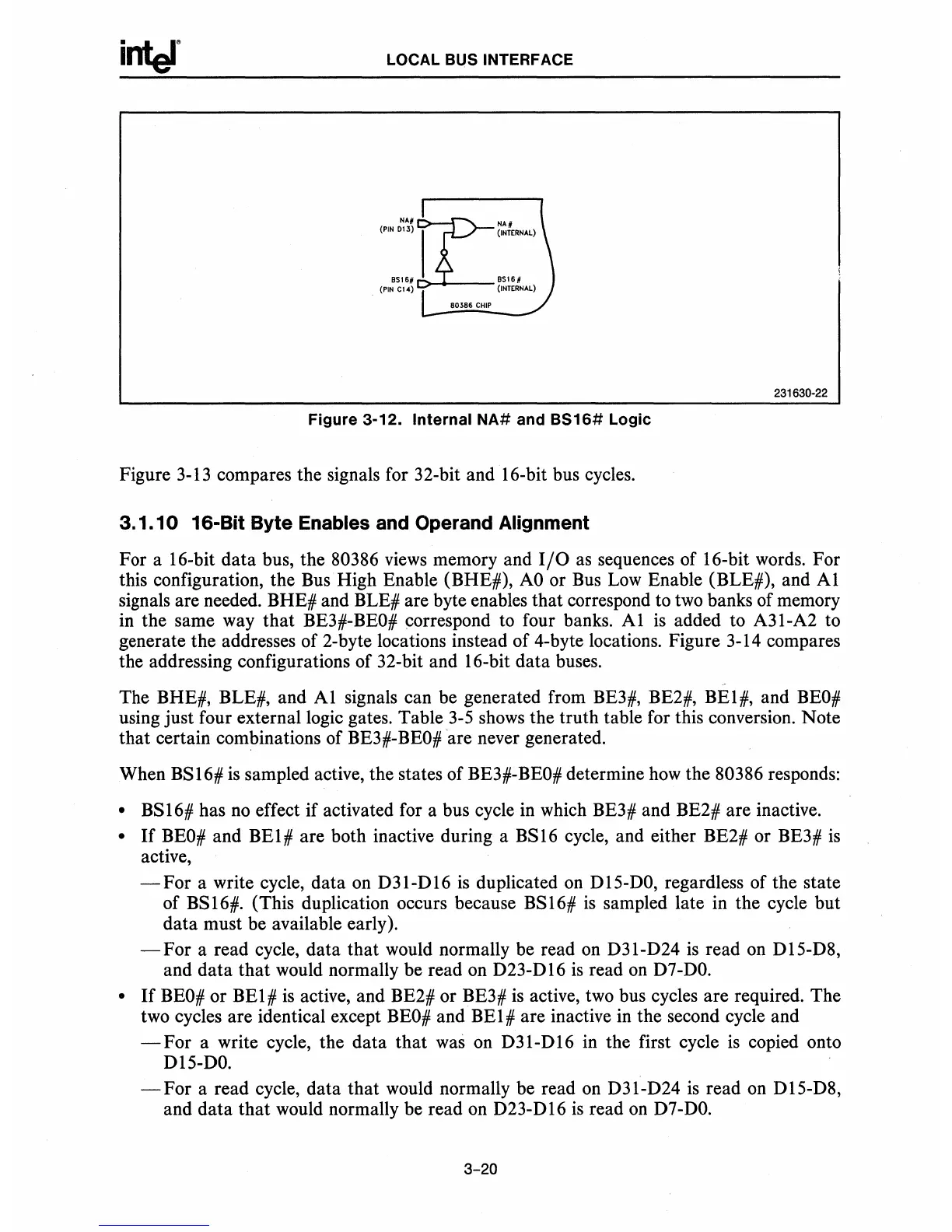
Figure
3-12.
Internal
NA#
and
Bs
16#
Logic
Figure
3-13
compares the signals for 32-bit and 16-bit bus cycles.
3.1.10
16-Bit
Byte
Enables and Operand Alignment
For a I6-bit data bus, the 80386
views
memory and
I/O
as
sequences of I6-bit words. For
this configuration, the
Bus
High Enable (BHE#),
AO
or
Bus
Low
Enable (BLE#), and
Al
signals are needed. BHE# and BLE# are byte enables that correspond to
two
banks of memory
in
the same way that BE3#-BEO# correspond to four banks.
Al
is
added to A3I-A2 to
generate the addresses of 2-byte locations instead of 4-byte locations. Figure 3-14 compares
the addressing configurations of 32-bit and 16-bit data buses.
The BHE#, BLE#, and
Al
signals can be generated from BE3#, BE2#, BE1#, and
BEO#
using just four external logic gates. Table
3-S
shows
the truth table for this conversion. Note
that certain combinations of BE3#-BEO#are never generated.
When BSI6#
is
sampled active, the states of BE3#-BEO# determine
how
the 80386 responds:
• BSI6# has
no
effect if activated for a bus cycle
in
which BE3# and BE2# are inactive.
•
If
BEO#
and
BEI#
are both inactive during a BS16 cycle, and either BE2# or BE3#
is
active,
-For
a write cycle, data
on
D3I-DI6
is
duplicated
on
DIS-DO, regardless of the state
of BSI6#. (This duplication occurs because BS16#
is
sampled late in the cycle but
data must be available early).
-For
a read cycle, data that would normally be read
on
D31-D24
is
read on DIS-D8,
and data that would normally be read on D23-D16
is
read
on
D7-DO.
•
If
BEO#
or BE1#
is
active, and BE2# or BE3#
is
active, two bus cycles are required. The
two cycles are identical except
BEO#
and BE1# are inactive in the second cycle and
-For
a write cycle, the data that was on
D3I-DI6
in the first cycle
is
copied onto
DIS-DO.
-For
a read cycle, data that would normally be read
on
D3I-D24
is
read on D1S-D8,
and data that would normally be read
on
D23-D
16
is
read
on
D7
-
DO.
3-20