RC
CIRCUIT
LOCAL
BUS
INTERFACE
30pF
HO:
'"~
200
pI
5pH
X, X,
~
RES# RESET
~
82384
F/C#
CLK2
r-
j"OO'
j'"
TO
SUPPORT
PERIPHERALS
RESET
CLK2
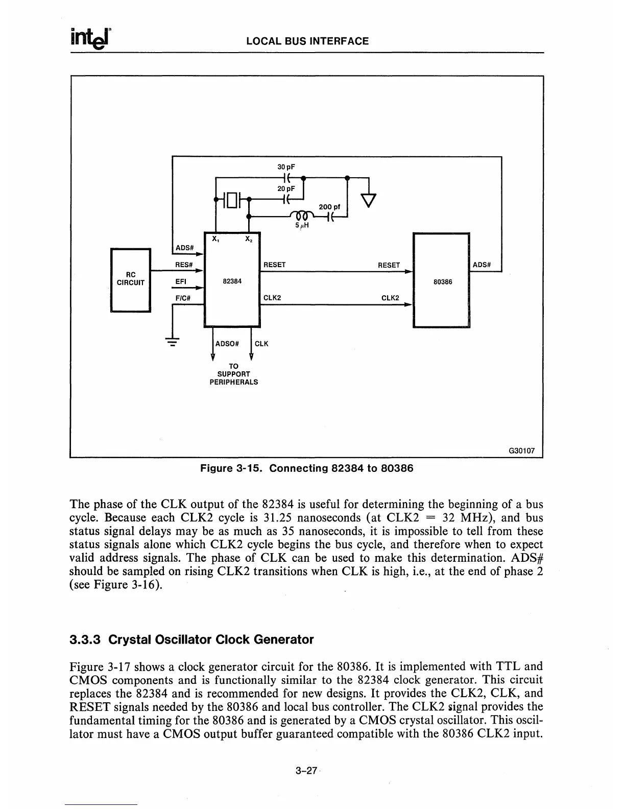
Figure
3-15.
Connecting
82384
to
80386
ADS#
-
80386
G30107
The phase of the CLK output of the 82384
is
useful for determining the beginning of a bus
cycle. Because each CLK2 cycle
is
31.25 nanoseconds
(at
CLK2 =
32
MHz), and bus
status signal delays may be as much as
35
nanoseconds, it
is
impossible to tell from these
status signals alone which CLK2 cycle begins the bus cycle, and therefore when to expect
valid address signals. The phase of CLK can be used to make this determination. ADS#
should be sampled
on
rising CLK2 transitions when CLK
is
high, i.e., at the end of phase 2
(see Figure 3-16).
3.3.3
Crystal Oscillator Clock Generator
Figure 3-17 shows a clock generator circuit for the 80386.
It
is
implemented with TTL and
CMOS
components and
is
functionally similar to the 82384 clock generator. This circuit
replaces the 82384 and
is
recommended for
new
designs.
It
provides the CLK2, CLK, and
RESET
signals needed by the 80386 and local bus controller. The CLK2
iiignal
provides the
fundamental timing for the 80386 and
is
generated by a CMOS crystal oscillator. This oscil-
lator must have a CMOS output buffer guaranteed compatible with the 80386 CLK2 input.
3-27