8XC196KC/8XC196KC20
270942–17
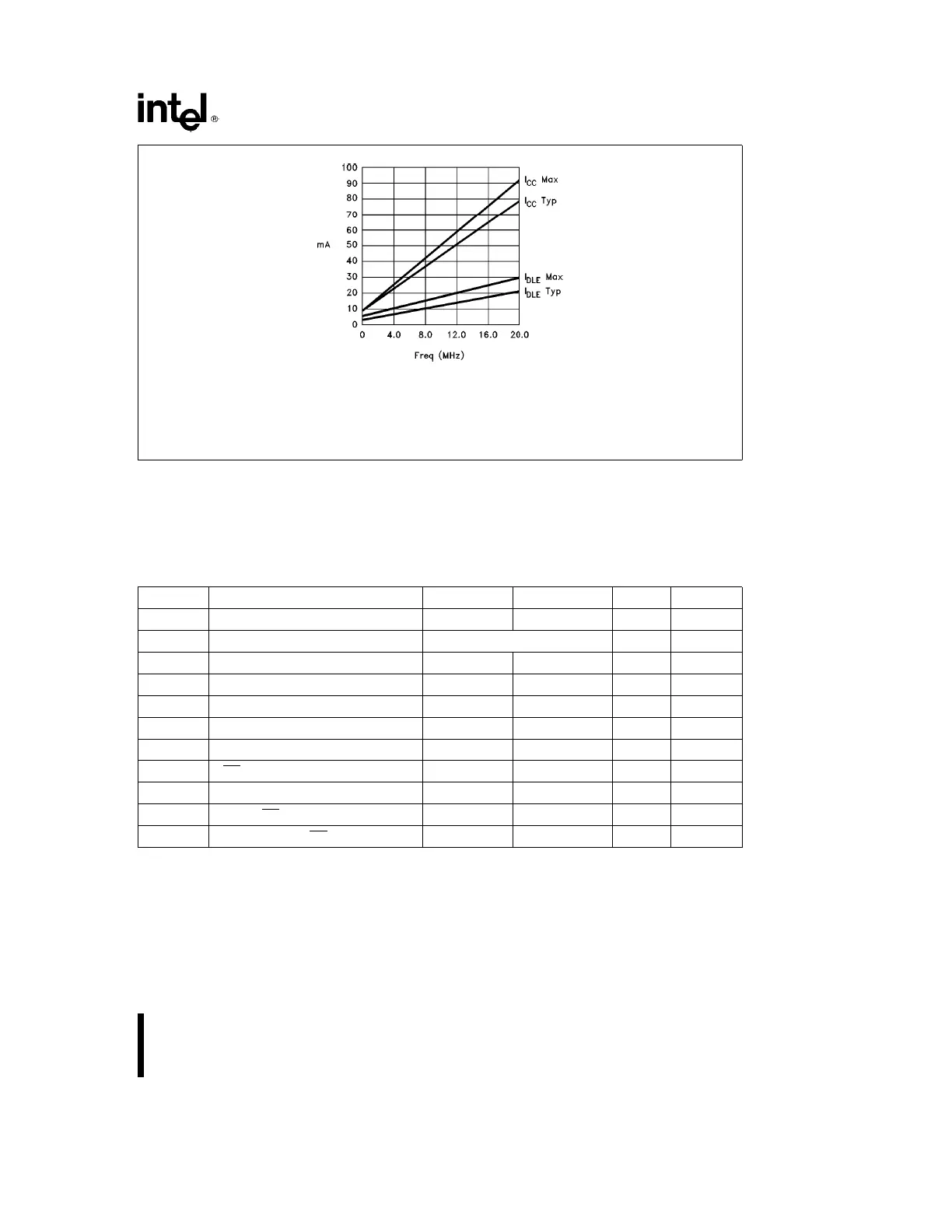
I
CC
Max
e
4.13
c
Frequency
a
9mA
I
CC
Typ
e
3.50
c
Frequency
a
9mA
I
IDLE
Max
e
1.25
c
Frequency
a
5mA
I
IDLE
Typ
e
0.88
c
Frequency
a
3mA
NOTE:
Frequencies below 8 MHz are shown for reference only; no testing is performed.
Figure 7. I
CC
and I
IDLE
vs Frequency
AC CHARACTERISTICS
For use over specified operating conditions.
Test Conditions: Capacitive load on all pins
e
100 pF, Rise and fall times
e
10 ns, F
OSC
e
16 MHz
The system must meet these specifications to work with the 80C196KC:
Symbol Description Min Max Units Notes
T
AVYV
Address Valid to READY Setup 2 T
OSC
b
68 ns
T
YLYH
Non READY Time No upper limit ns
T
CLYX
READY Hold after CLKOUT Low 0 T
OSC
b
30 ns (Note 1)
T
LLYX
READY Hold after ALE Low T
OSC
b
15 2 T
OSC
b
40 ns (Note 1)
T
AVGV
Address Valid to Buswidth Setup 2 T
OSC
b
68 ns
T
CLGX
Buswidth Hold after CLKOUT Low 0 ns
T
AVDV
Address Valid to Input Data Valid 3 T
OSC
b
55 ns (Note 2)
T
RLDV
RD Active to Input Data Valid T
OSC
b
22 ns (Note 2)
T
CLDV
CLKOUT Low to Input Data Valid T
OSC
b
45 ns
T
RHDZ
End of RD to Input Data Float T
OSC
ns
T
RXDX
Data Hold after RD Inactive 0 ns
NOTES:
1. If max is exceeded, additional wait states will occur.
2. If wait states are used, add 2 T
OSC
* N, where N
e
number of wait states.
11