Chapter 4 Installation
4.1 Jumper Setting and Slot
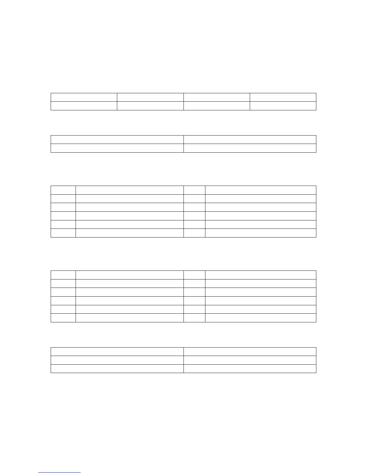
FSB CPU Frequency Jumper Setting
JUMPER AUTO (Default) 400 533
JP1 1-2 2-3 OPEN
JP3: Clear CMOS Jumper Setting
1-2 (Default) Normal
2-3 Clear CMOS
Audio: Front panel Jumper setting
PIN Function PIN Function
1 MIC+ 2 Ground
3 Vbias 4 AuD_Vcc (AVCC)
5 AuD_R_Out 6 AuD_R_Out Back
7 N.C. 8 Key
9 AuD_L_Out 10 AuD_L_Out Back
Note: 5-6, 9-10 pin short is default. (Reference main board bitmap)
USB: Expansion Connector
PIN Function PIN Function
1 VCC: Power 2 Ground
3 D-: Data – Signal 4 AuD_Vcc (AVCC)
5 D+: Data + Signal 6 AuD_R_Out Back
7 GND: Ground 8 Key
9 KEY 10 AuD_L_ Back
Expansion Slots
DDR1/DDR2 184 Pin DDR Memory Slots
PCI1/PCI2/PCI3 32 bit PCI BUS Expansion Slots
Socket 478 Socket 478 CPU Slots