Product Description
31
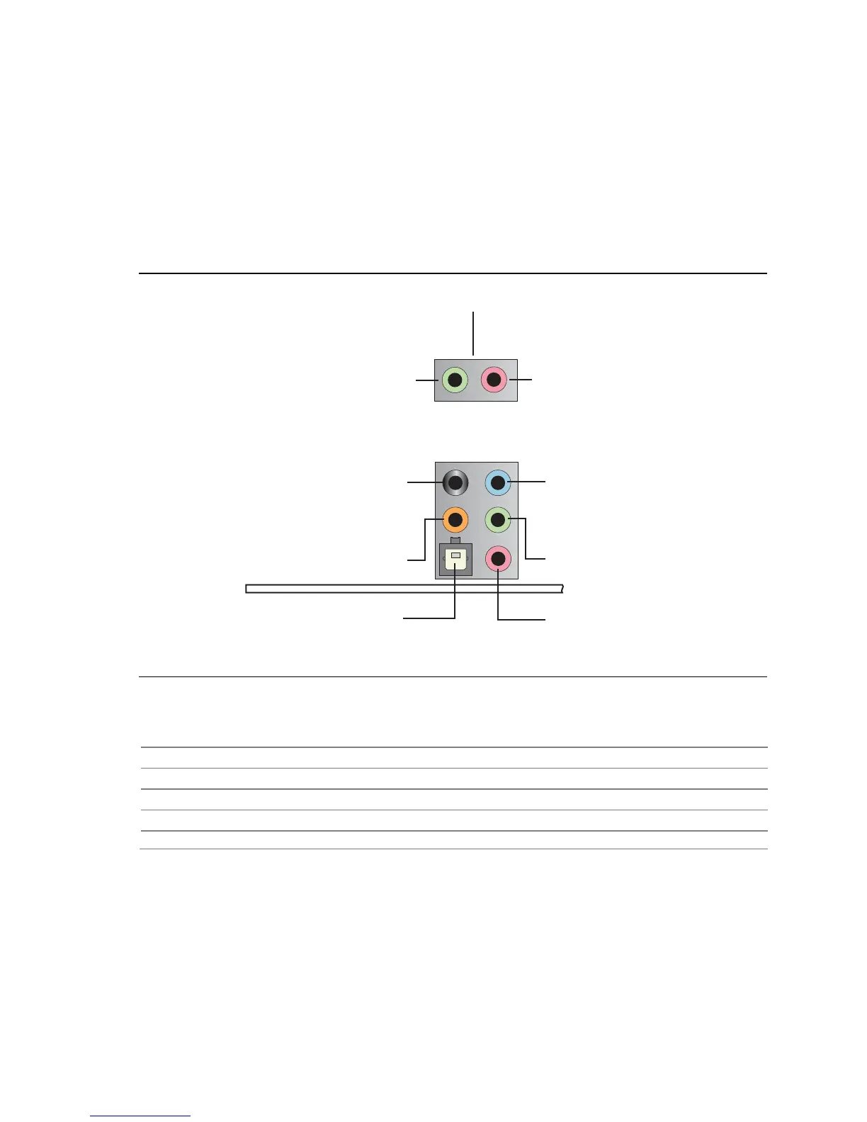
1.7.2 Audio Connectors and Headers
The board contains audio connectors on the back panel and audio headers on the
component side of the board. The front panel audio header provides mic in and line
out signals for the front panel. Microphone bias is supported for both the front and
back panel microphone connectors.
The front/back panel audio connectors are configurable through the audio device
drivers. The available configurable audio ports are shown in Figure 10.
OM18352
Surround Left and Right/
Retasking Jack
[Black]
Side Surround
Left and Right/
Line In/Retasking Jack
[Blue]
S/PDIF Digital Audio Out
Optical
Mic In/Retasking Jack
[Pink]
Line Out/Retasking Jack
[Green]
Mic In/Retasking Jack
[Pink]
Line Out/Retasking Jack
[Green]
Front Panel Audio Connectors
[Routed from Front Panel Audio Header]
Center channel and
LFE (Subwoofer)/Retasking Jack
[Orange]
Figure 10. Front/Back Panel Audio Connector Options
For information about Refer to
The location of the front panel audio header Figure 16, page 52
The signal names of the front panel audio header Table 26, page 55
The location of the HD Audio Link header Figure 16, page 52
The signal names of the HD Audio Link header Table 19, page 54
The back panel audio connectors Section 2.7.1, page 51