Installing and Replacing Desktop Board Components
45
Front Panel USB 2.0 Header
Figure 16, G shows the location of the front panel USB 2.0 header and Table 11 shows
the pin assignments and signal names.
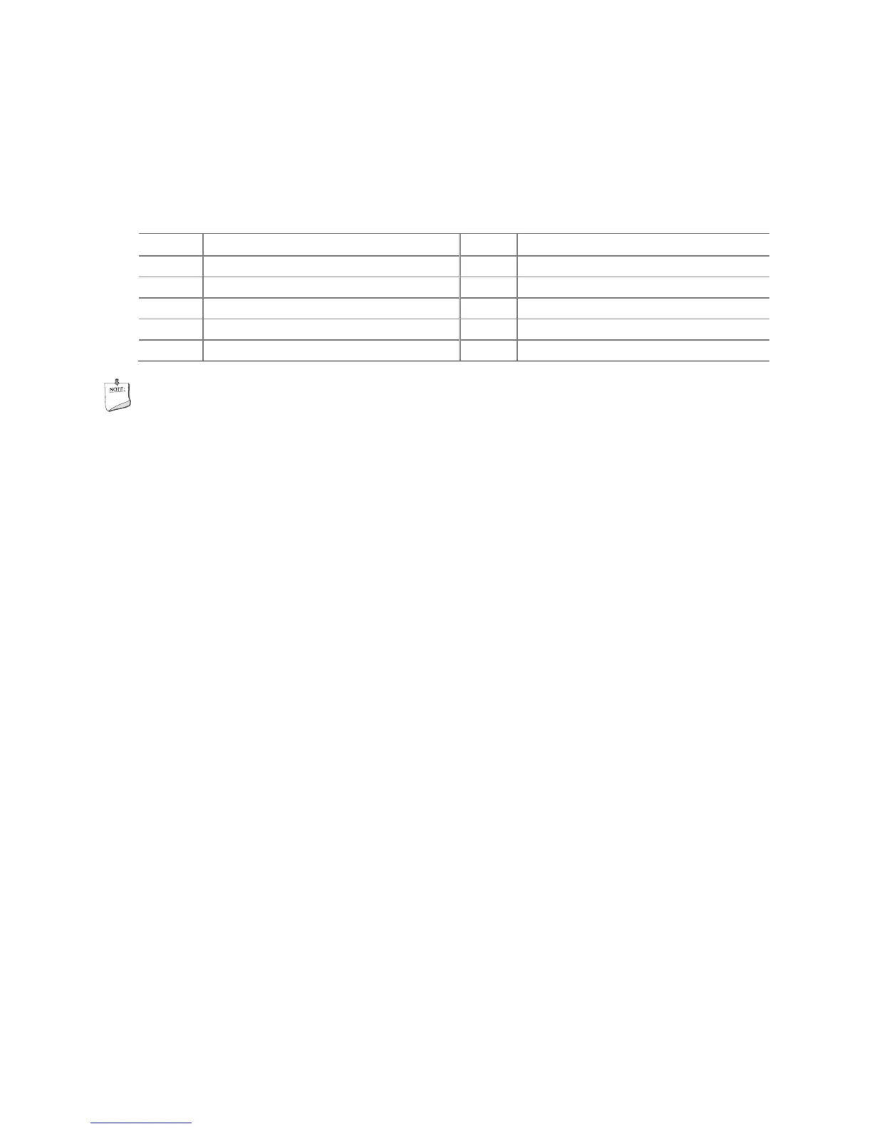
Table 11. Front Panel USB 2.0 Header Signal Names
Pin Signal Name Pin Signal Name
1 Power (+5 V) 2 Power (+5 V)
3 D- 4 D-
5 D+ 6 D+
7 Ground 8 Ground
9 Key 10 No Connection
NOTE
Computer systems that have an unshielded cable attached to a USB port might not
meet FCC Class B requirements, even if no device or a low-speed USB device is
attached to the cable. Use a shielded cable that meets the requirements for a
full-speed USB device.