Technical Reference
43
2.2.2.1 Signal Tables for the Connectors and Headers
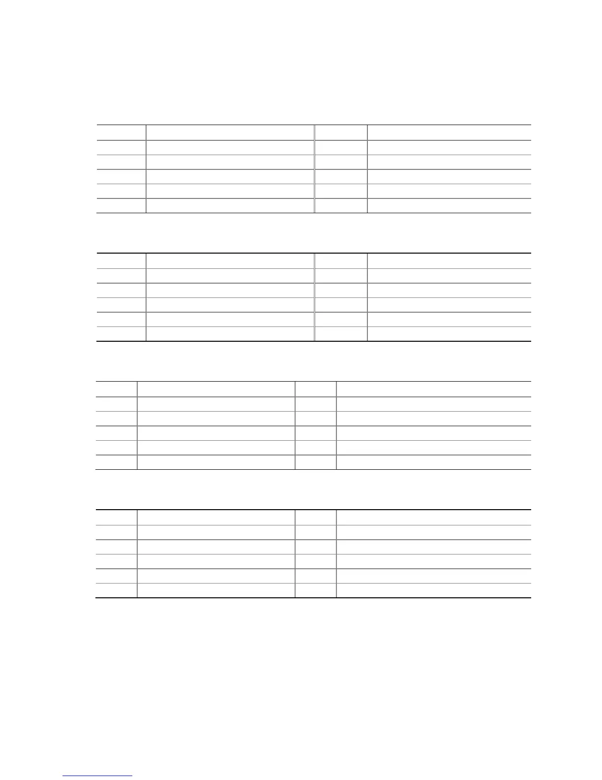
Table 11. IEEE 1394a Header
Pin Signal Name Pin Signal Name
1 Data A (positive) 2 Data A (negative)
3 Ground 4 Ground
5 Data B (positive) 6 Data B (negative)
7 +12 V DC 8 +12 V DC
9 Key (no pin) 10 Ground
Table 12. Front Panel Audio Header for Intel HD Audio
Pin Signal Name Pin Signal Name
1 [Port 1] Left channel 2 Ground
3 [Port 1] Right channel 4 PRESENCE# (Dongle present)
5 [Port 2] Right channel 6 [Port 1] SENSE_RETURN
7 SENSE_SEND (Jack detection) 8 Key (no pin)
9 [Port 2] Left channel 10 [Port 2] SENSE_RETURN
Table 13. Front Panel Audio Header for AC ’97 Audio
Pin Signal Name Pin Signal Name
1 MIC 2 AUD_GND
3 MIC_BIAS 4 AUD_GND
5 FP_OUT_R 6 FP_RETURN_R
7 AUD_5V 8 KEY (no pin)
9 FP_OUT_L 10 FP_RETURN_L
Table 14. Front Panel USB Headers
Pin Signal Name Pin Signal Name
1 +5 V DC 2 +5 V DC
3 D- 4 D-
5 D+ 6 D+
7 Ground 8 Ground
9 KEY (no pin) 10 No Connect