Intel Desktop Board DQ77MK Technical Product Specification
14
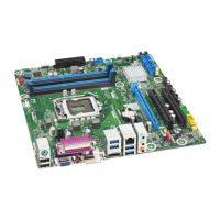
Table 2 lists the components identified in Figure 1.
Table 2. Components Shown in Figure 1
Item/callout
from Figure 1
Description
A PCI Express x4 add-in card connector
B Conventional PCI add-in card connector
C IEEE 1394 a front panel header
D PCI Express x1 add-in card connector
E PCI Express x16 add-in card connector
F Back panel connectors
G 12 V processor core voltage connector (2 x 2 pin)
H LGA1155 processor socket
I Rear chassis fan header
J Processor fan header
K DIMM 3 (Channel A DIMM 0)
L DIMM 1 (Channel A DIMM 1)
M DIMM 4 (Channel B DIMM 0)
N DIMM 2 (Channel B DIMM 1)
O Front chassis fan header
P Low Pin Count (LPC) Debug header
Q Chassis intrusion header
R Main power connector (2 x 12)
S Intel
®
Management Engine BIOS Extension (Intel
®
MEBX) Reset header
T Battery
U Piezoelectric speaker
V Intel
®
Management Engine “M” state LED
W PCI Express Full-/Half-Mini Card slot
X SATA 6.0 Gb/s connector (multiplexed with an mSATA port, routed to the PCI
Express Full-/Half-Mini Card slot) (gray)
Y SATA 3.0 Gb/s connectors through the PCH (black)
Z Alternate front panel power/sleep LED header
AA Front panel connector
BB Standby power LED
CC BIOS Setup configuration jumper block
DD SATA 6.0 Gb/s connectors through the PCH (blue)
EE Front panel USB 3.0 connector (blue)
FF Intel Q77 Express Chipset
GG Front panel USB 2.0 connector
HH Front panel USB 2.0 connector
II Serial port connector
JJ S/PDIF out header
KK Front panel audio connector
LL Internal mono speaker header
 Loading...