11
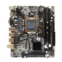
System Case Connections
HDLED
RESET
VC C5
GN D
VCC5
PWR LED
PWRBTN
PWRBTN
PWRLED
HDDLE
RSTSW
NC
GND
JW FP
Pin 1
SPEAK
SPKR
GND
NC
VCC5
Pin 1
PWRLED
Pin 1
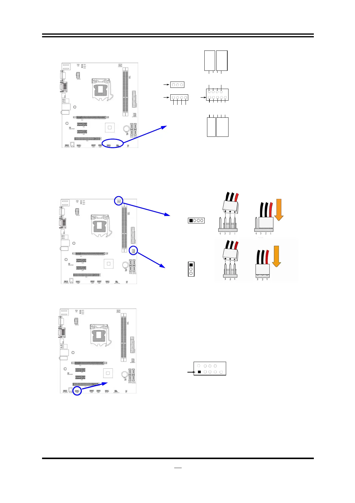
(8) FAN Headers: SYSFAN1, (3-pin), CPUFAN1 (4-pin)
These connectors support cooling fans of 350mA (4.2 Watts) or less, depending
on the fan manufacturer, the wire and plug may be different. The red wire
should be positive, while the black should be ground. Please connect the fan’s
plug to the board taking into consideration the polarity of connector.
SYSFAN1
3
1
14
CPUFAN
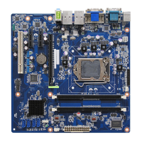
(9) S
erial COM Port header:
COM1
COM1 is a 9-pin block header.
Serial COM Port 9-pin Block
Pin1
(10) SPDIF Out header: HDMI_SPDIF1
The SPDIF output is capable of providing digital audio to external speakers or
compressed AC3 data to an external Dolby digital decoder. Use this feature only
when your stereo system has digital input function.