EasyManua.ls Logo

Intel Optane SSD 900P Series User Manual

Intel Optane SSD 900P Series
3 pages
To Next Page IconTo Next Page
Page #1 background imageLoading...
Page #1 background image
Physical Installation Instructions for Intel® Optane™ SSD 900P Series
See the instructions below for how to install the Intel® Optane™ SSD 900P Series hardware.
The PCIe* NVMe*-based SSD requires specific support from your motherboard or system
vendor. Check with your vendor before proceeding.
Before you begin
Caution
Disconnect the desktop board's power supply from its AC power source before you
connect cables, disconnect cables, install, or remove any board components.
Without first disconnecting the power supply, you risk personal injury or equipment
damage.
Some circuitry on the desktop board can operate even if the front panel power switch
is off.
Electrostatic discharge (ESD) can damage desktop board components. Install the board
at an ESD-controlled workstation. If an ESD-controlled workstation is unavailable,
wear an anti-static wrist strap or touch the surface of the anti-static package before
handling the board.
Prepare
Your board may have multiple PCIe* slots. The PCIe SSD needs a PCI Express* (PCIe) x4 or
higher connector. Best performance is with a PCIe 3.0 connector.
In our example:
Install the PCIe SSD in connector A, B, C, or F
For best performance, we recommend the connector closest to the processor/CPU (F)
Question and Answer IconNeed help?

Do you have a question about the Intel Optane SSD 900P Series and is the answer not in the manual?

Intel Optane SSD 900P Series Specifications

General IconGeneral
Capacity280 GB, 480 GB
Sequential Read Speed2500 MB/s
Random Read IOPSUp to 550, 000 IOPS
Random Write IOPS500, 000 IOPS
Latency - Read10 µs
Latency - Write10 µs
MTBF1.6 million hours
Warranty5 years
InterfacePCIe 3.0 x4
Form FactorAdd-in Card (AIC), 2.5-inch U.2
Power Consumption (Idle)5W

Summary

Before You Begin

Power Safety Precautions

Disconnect the desktop board's power supply from its AC power source before handling components to prevent injury or damage.

ESD Handling

Protect components from electrostatic discharge by using an ESD-controlled workstation or an anti-static wrist strap.

Prepare for Installation

PCIe Connector Requirements

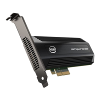
The PCIe SSD needs a PCIe x4 or higher connector; best performance is with a PCIe 3.0 connector.

Installation Steps for Add-in Card

Add-in Card Installation

Find proper PCIe 3.0 connector, attach SSD to I/O shield, insert SSD, and secure with chassis screw.

Installation Steps for 2.5-inch U.2 Drive

U.2 Drive Connection

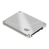
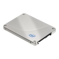
Mount SSD, connect cable to U.2 connector, connect M.2 or SFF 8643 card, and connect SATA power.

Connector Notes

Mini-SAS HD/M.2 Connector Type

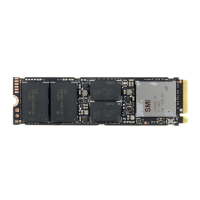
Ensure mini-SAS HD/M.2 connector is PCIe, not SAS or SATA, as NVMe SSDs only support PCI Express signals.

Related product manuals