Intel® RAID Controller RS2WG160 Hardware User’s Guide 11
3 Intel
®
RAID Controller RS2WG160
Characteristics
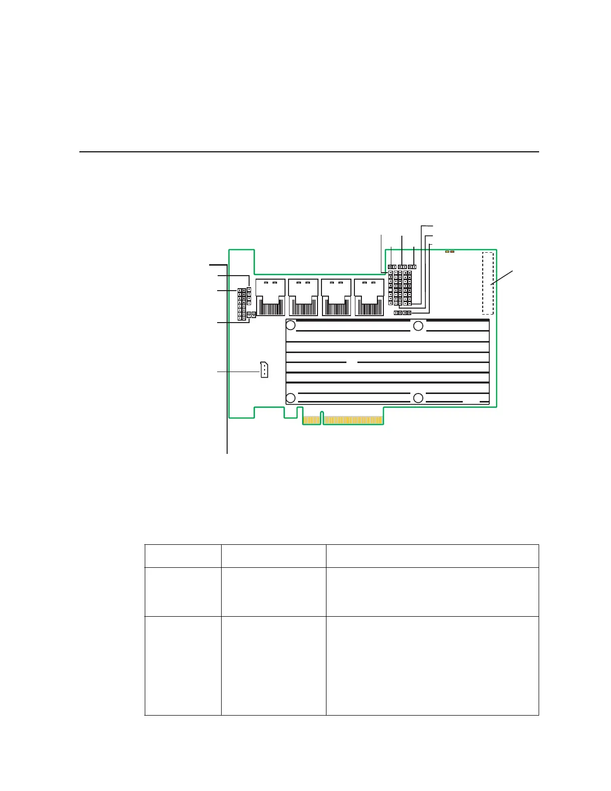
Figure 3. Card Layout
Table 1. Jumper Description
s
Jumper Type Description
J1A2 Universal Asynchronous
Receiver/ Transmitter
(UART) for the
Expander
4-pin connector. Reserved for factory use.
J1B1 LED Locate and Fault
Indication header
Ports 0-3
Ports 4-7
2x8-pin connector. Connects to an LED that indi-
cates whether a drive is in a fault condition. There
is one LED per port. When lit, each LED indicates
the corresponding drive has failed or is in the
unconfigured-bad state.
The LEDs function in a direct-attach configuration
(there are no SAS expanders). Direct attach is
defined as a maximum of one drive connected
directly to each port.
J2B1
Ports
0-3
J2B2
Ports
4-7
J3B1
Ports
8-11
J4B2
Ports
12-15
J1A2
J1B1
J1B3
J1C1
J2D1
J4A2
J5A2
J4A3
J5B3
J4A1
J4A4
J4A5
AF003504
J1L1
on back