9
4. Installation of the alarm center and its peripheral devices
Attention: only connect the central to the mains and battery after installing all the equipment and peripheral devices.
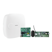
Open the product box and then open the alarm center cabinet cover by removing the screws, where you will be able to see
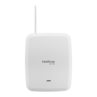
two plates, that is, its basic conguration contains the AMT 8000 LITE or AMT 8000 PRO alarm center plate and its respective
power supply and the rechargeable battery that comes with the alarm center.
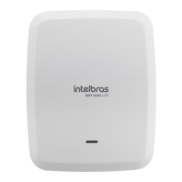
You can purchase the XG 2G, XG 3G and XG 4G modules for the AMT 8000 LITE alarm center and the XG 2G, XG 3G, XG 4G
and FXO 8000 modules for the AMT 8000 PRO, and these boards have their respective interconnection cables with the alarm
center.
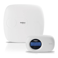
The AMT 8000 LITE and AMT 8000 PRO alarm center have only wireless zones, as well as other accessories (keyboard, sirens,
etc.) are connected to the alarm center via a wireless signal, with only the AC power and Ethernet cables connected to alarm
center.
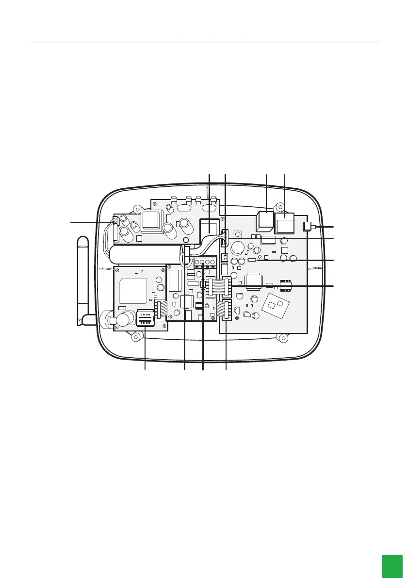
The following image illustrates the alarm center with all the devices that can be physically connected:
13
1
2
3
5
6
7
8
12
11 10 9
4
AMT 8000 LITE/PRO alarm control
1. Opening for passing the Ethernet cable and telephone line (AMT 8000 PRO compatibility).
2. Integrated siren connection.
3. Connector for Ethernet network cable.
4. WI-FI Module (AMT 8000 PRO compatibility).
5. Button for registering wireless devices.
6. Connector for power supply at cable.
7. Micro-USB type connector for updating the alarm control panel’s rmware.
8. Connector for FXO 8000 module at cable (AMT 8000 PRO compatibility).
9. Connector for at cable of XG 2G, XG 3G and XG 4G modules.
10. Connector for connecting the telephone line and telephone (AMT 8000 PRO compatibility).
11. FXO 8000 board ground point (AMT 8000 PRO compatibility).
12. Connector for SIM 1 and SIM 2 card.
13. Input connector for battery connection.
Note:
XG 2G, XG 3G and XG 4G modules are compatible with most national GSM operators with 2G, 3G and 4G
technology.
 Loading...