131 Eisenhower Lane North
Lombard, IL 60148
630.268.0010 / 1.800.251.2408
P/N 53-00684-200 Rev. A 071301
www.Intellitecsve.com
Intellitec
INSTALLATION & SERVICE MANUAL
TM
50 AMP Smart Energy Management System Model 900
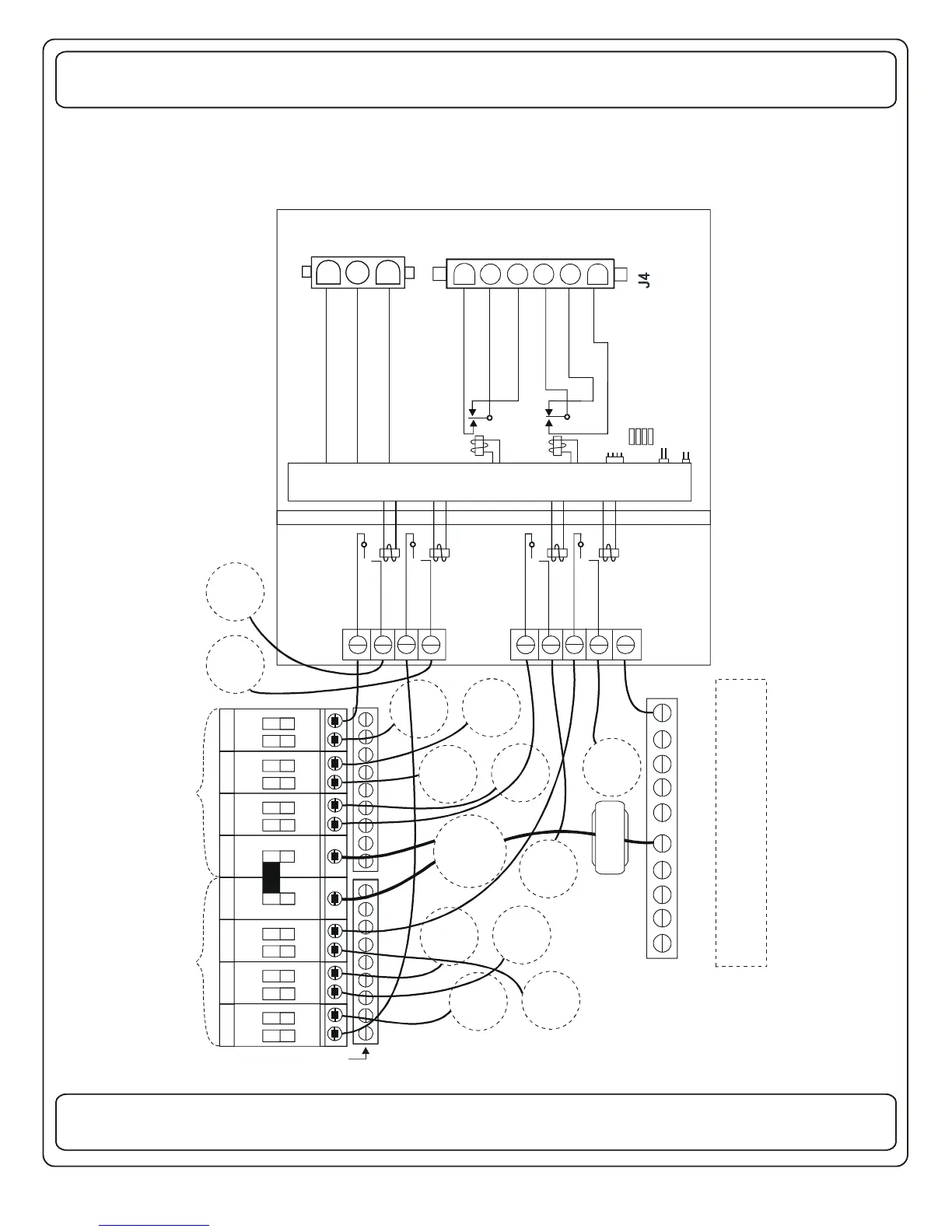
BRKR #2
RELAY #2
BRKR #1
RELAY #1
NEUTRAL
LINE 2
LINE 1
L
I
N
E
1
L
I
N
E
2
12 VOLT SIDE
EMS
CIR 3
50A 50A
EMS
CIR 1
EMS
CIR 2
EMS
CIR 4
J3 To Current Sensor
120/240 VOLT SIDE
BRKR #4
RELAY #4
BRKR #3
RELAY #3
EMS Controlled
Loads 1HP, 15A,
1 20 VA C, 60 H Z
ENERGY MANAGEMENT
CONTROL ELECTRONICS
BARRIER
RELAY #5 N.O.
RELAY #5 COM
RELAY #5 N.C.
RELAY #6 COM
RELAY #6 N.C
RELAY #6 N.O.
Remote Display Connector
AIR-CONDITIONERS
THERMOSTAT LEADS
LOAD 1.0A, 24VDC
OPTION JUMPER:
SEE OWNERS GUIDE
J5
J2
+12 VOLTS
+12V GEN RUN
GROUND
_
INSULATED NEUTRAL
All 120/240 VAC Neutral current must
pass thru EMS Current Sensor.
50/30A
MAIN
J1 Hi-Pot Test
CURRENT
SENSOR
1
2
3
1
2
3
4
5
6
TYPICAL WIRING DIAGRAM
LINE 1
GROUND BLOCKS
LINE 2
N
E
U
T
R
A
L
 Loading...