53‐01130‐200RevA06/09/20
Page3
INSTALLATIONGUIDE
LocatingtheBatteryGuard®1000Switch:
TheBatteryGuard®1000offersadirectswitchinputsignalthatallowstheusertotoggletheprimarydisconnectstate.
ThiscanbecomeveryusefuliftheRV‐Cnetworkweretoevergodownoriftheuserdoesnothaveaccesstotheother
controlmethods.Theswitchshouldbereadilyaccessiblebytheuser.Thisswitchnotonlycontrolsthestateofthe
batterydisconnectbutalsoprovidesindicationofthedisconnectstateandwhetherfaultshaveoccurred.Ensurethe
wallusedformountingtheswitchhasenoughclearancebehindittoallowcablesaccess.Typically,¾”to1”isrequired.
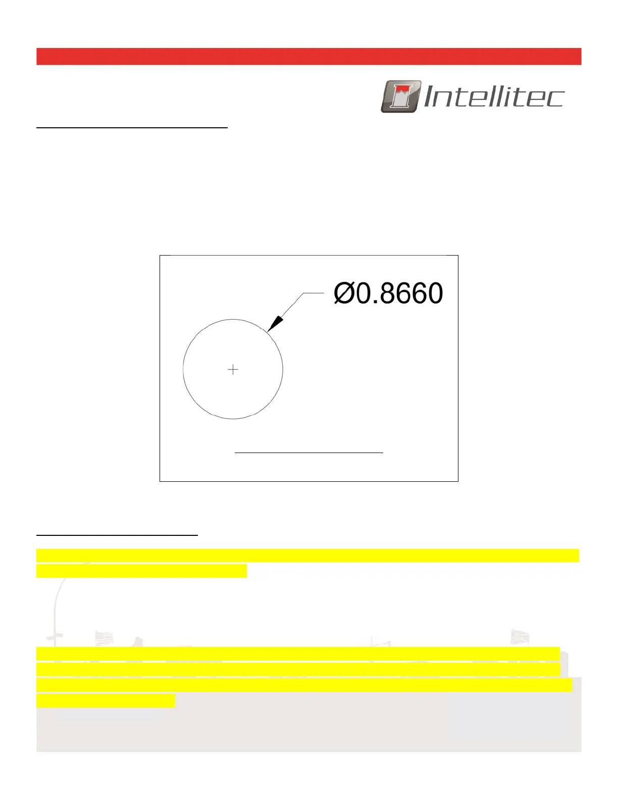
(Dimensionsininches)
RECOMMENDEDPANELCUTOUT
MaxPanelthicknessshouldnotexceed0.3inches
Note:DrawingdimensionsrefertotheswitchusedintheIntelliteckit(part#10‐01130‐000).
InstallingtheBatteryGuard®1000:
WARNING:Beforeproceeding,disconnectallsourcesofpower.Unplugtheshorepowercableandturnoffthegenerator.
Disconnectthebattery(s)negative(‐)terminal.
TheBatteryGuard®1000controlsarelaythatactsaselectro‐mechanicalswitchthatdisconnectsthebattery.Itshould
belocatednearthebatteryforwiringsimplicity.Wheninstalled,therelaywillbeinserted"in‐line"withthecable
comingfromthepositive(+)terminalofthebattery.Keepthisinmindwhenchoosingtheinstallationlocation.
WARNING:Topreventunwantedisolationwhenignitionsignalispresent,theBatteryGuard®1000looksattheRV‐C
networktodetermineitsignitioninhibitstate.Ensurethenetworkintegrationsupportsthe“ignitionswitchstatus”if
attachingoperationsafetycriticaldevices.Ifnot,itisrecommendedthatsafetycriticaldevicesbeonaseparatebranch
fromtheBatteryGuard®1000.
 Loading...