2 – DP 9002 Intellitronix (rev. 09/10/2020BB) www.intellitronix.com
DASHBOARD REMOVAL AND INSTALLATION
Disassembly
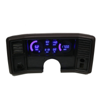
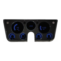
1. Remove the existing dash cluster from the vehicle. Separate the front bezel from the back
housing and gauges.
2 Remove the bezel, inner gauge frame and gauges from the old assembly.
3 Attach the acrylic lens to the front of the panel, using provided mounting kit.
4. Attach the new panel to the front of the housing, and re-insert the frame into the housing,
and reattach to the bezel, re-using the original screws and other hardware.
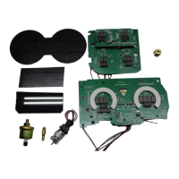
5. Wire the gauges and sending units to the panel as indicated by the instructions below.
See the back of this guide for some Illustrations on assembly.
WIRING INSTRUCTIONS
Note: Automotive circuit connectors are the preferred method of connecting wires. However, you
may solder if you prefer.
Note: LS Engines or any other Computer based engine systems most use provides sensors and
install new wires to new sensors
Note: If doing a LS engine swap, pick up the tach signal wire from the ECM/ECU and then set
the tach switch to 4-cylinders. You may also need to order the Intellitronix LS Engine Swap
Adapter Kit for Series 1, 2 and 3 engines. The part number is 8014LS. If you are getting the tach
signal from the ECU, the resistor in the adapter kit will help pull a stronger signal for the
tachometer. If your engine is a LS the Tachometer will need to be put into 4 cylinder mode by
removing Resistors if the Tachometer does not have a push button for programing, please call
Tech Support at Intellitronix, as you may need to send the gauge back to us to be reconfigured.
There is no charge for this additional service.
Ground – Black--This is the main ground for the display system. A wire should be run from
this board to the vehicle engine block for the best ground. Use 18 AWG or larger wire to
ensure sufficient grounding. Proper vehicle grounding is extremely important for any gauges (or
electronics) to operate correctly. The engine block should have heavy ground cables to the
battery, frame, and firewall. Failure to properly ground the engine block, senders, or digital dash
can cause incorrect or erratic operation.
Power - Red--Connect the power terminal to accessory +12V power from the fuse panel or vehicle
wiring harness. Using a 5-amp fuse or an inline 5-amp fuse holder. This terminal should have power
when the key is on or in accessory position. Use 18 AWG wire to ensure the system receives a
sufficient power feed.
 Loading...