EasyManua.ls Logo

Intellitronix DP6004 - User Manual

Intellitronix DP6004
11 pages
Print Icon
To Next Page IconTo Next Page
Loading...
1 DP6004 Intellitronix rev.04/10/20) www.intellitronix.com
Made in America Lifetime Guarantee
Thank you for purchasing this instrument panel from Intellitronix. We value our customers!
INSTALLATION GUIDE
Chevrolet-GMC Digital Dash Panel
Part Number: DP6004
Year Series: 1973 1987
Always disconnect the battery before attempting any electrical work on your vehicle.
KIT COMPONENTS
Three (3) Digital Circuit Boards (speedo, tach on one board; two smaller boards already
assembled; Voltmeter and Oil pressure on one, Fuel and Water Temperature on the other.)
Three (3) Smoked Acrylic Lenses
* Peel off protective covering from both sides of each lens
One (1) Temperature Sending Unit (S8013) - 1/8” NPT, 0-255 Deg., 1/2” NPT Bushing
One (1) Pressure Sending Unit (S8434) - 1/8” NPT, 0-100 PSI Oil Pressure
One (1) Universal Speedometer Sensor (S9013) - 7/8” NPT Industry Standard threads
One (1) Mounting Kit 2 pcs double-sided sticky tape (This for holding lens in place, 4 Nylon
washers for spacing gauge cover only if needed.)
Gauge Hardware kit board has 2 #4 x ¾ Bolts 2 - #4 x1/4 spacers 2 Nylock nuts
Question and Answer IconNeed help?

Do you have a question about the Intellitronix DP6004 and is the answer not in the manual?

Intellitronix DP6004 Specifications

General IconGeneral
Display TypeDigital
Input Voltage12V
Bezel ColorBlack
Product TypeDigital Gauges
Gauge TypeOil Pressure
Operating Temperature-40°F to 185°F
Mounting TypeDash Mount

Summary

Installation Guide

Kit Components

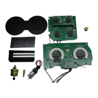
Lists all included parts for the digital dash panel installation.

Dash Panel Installation Instructions

Step 1: Remove and Place Circuit Board

Remove existing gauges and place the new circuit board into the stock housing.

Step 2: Mount Circuit Board

Modify mounting posts and screw the circuit board into place using acrylic washers.

Step 3: Wiring Circuit Boards

Connect the circuit boards following wiring instructions, using existing or separate wires.

Step 4: Install Bezel and Lenses

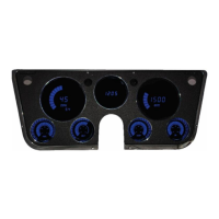
Place the factory bezel and smoked acrylic lenses over the circuit boards and secure.

Wiring Instructions

Ground Wire (Black)

Connect the black wire to the vehicle engine block for proper grounding.

Accessory Power (Red;Pink)

Connect red/pink wire to accessory +12V power from fuse panel or harness.

Constant Battery Power (Red)

Connect red wire to constant +12V power from the battery source.

Wiring Connections for Gauges

Oil Pressure (Orange)

Connect the orange wire to the oil pressure sending unit.

Water Temperature (Blue)

Connect the blue wire to the water temperature sending unit.

Turn Signals (Grey)

Connect grey wires to left and right turn signal indicator circuits.

Brake Light (Tan)

Connect tan wire to parking brake light switch.

Check Engine Light (Green;Yellow)

Connect green/yellow wire to Check Engine Light circuit.

Fuel Gauge Setup and Testing

Fuel Sender Wiring (Yellow)

Connect the yellow wire to the factory fuel sending unit.

Fuel Sender Ohm Range Settings

Configure dip switches based on fuel sender manufacturer and ohm range.

Fuel Gauge Test Procedure

Test fuel gauge continuity and OHMS to sender for proper operation.

Tachometer Installation and Settings

Tachometer Wiring (Green)

Connect green wire to the negative (-) side of the ignition coil.

Ignition System Compatibility

Details connections for various ignition systems like GM HEI, Magneto, etc.

Tachometer Settings Adjustment

Guide to adjust RPM display, cylinder count, and max RPM settings.

Speedometer Installation and Features

Speedometer Wiring (White)

Connect white wire from factory or Intellitronix sender to gauge.

PCM;ECM Speed Signal

Utilize PCM/ECM for speed signal on computer-controlled engines.

Digital Speedometer Functions

Overview of odometer, trip meter, high speed recall, and 0-60 time.

Speedometer Calibration

Calibration Preparation

Ensure proper installation and wiring before attempting calibration.

Calibration Procedure Steps

Guide to calibrate the speedometer using a measured mile and recall button.

Calibration Warning

Do not move the vehicle if 'CAL' mode is active; it may cause data loss.

Advanced Features and Data

Trip Distance Meter

Activate and clear the trip meter using the recall button.

Setting the Odometer

Enter the vehicle's actual mileage into the odometer setting.

Recording and Viewing Performance Data

Record and recall data like high speed, 1/4 mile ET, and 0-60 time.

Technical Support and Warranty

Technical Support Information

Contact details and hours for Intellitronix technical support.

Support Website

Visit the Intellitronix support page for quick answers and FAQs.

Limited Lifetime Warranty

Details the terms of the product's limited lifetime warranty.

Return Policy Procedures

Return Policy Instructions

Steps for returning a product, including RMA number and packaging.

Request for Product Refund

Conditions for refunds, including restocking fees and proof of purchase.

Related product manuals