4 – DP 9002 Intellitronix (rev. 09/10/2020BB) www.intellitronix.com
Note: FUEL GAUGE TEST The most common problem with our Fuel Gauge not working is the
circuit is not complete. The easiest way to test this is to use a voltmeter and test for continuity on
wires going to fuel sender. With wire disconnected from Fuel Gauge check for continuity to
ground. Without this the Gauge will not work.
Voltage Gauge – This Gauge Requires no wire hookup. Volt Gauge is built into the dash panel
and is powered by the main power and ground connection of the dash. It does have an Adjuster to
fine tune the voltage. Note: you will need to adjust it before fully installing the dash
SPEEDOMETER
Speedometer – White - (Factory sender with Powertrain Control Module) When using a LS
engine swap, you will need to pick up the Speedometer signal wire from the PCM Pin 50 on the
red connector. (This pin may Differ. Refer to your vehicles Pinout Chart for accuracy). Any other
Computer based engine will need to use to use the PCM/ECM to run the speed signal for the
Speedometer. (Consults Pinout)
Speedometer – White - (Factory two wire sender no PCM) - Most vehicles built after 1984 have
an electronic transmission sender. If your vehicle is already equipped with an electronic
transmission, then the electronic vehicle sender will usually have Two wires attached to it. One
connects to the Signal wire on dash (we prefer this to be high output). The other wire (Low output)
Ground at the Engine block. To find High and Low output wire color or pin location will need to
be looked up by Vehicle vin or Model and year.
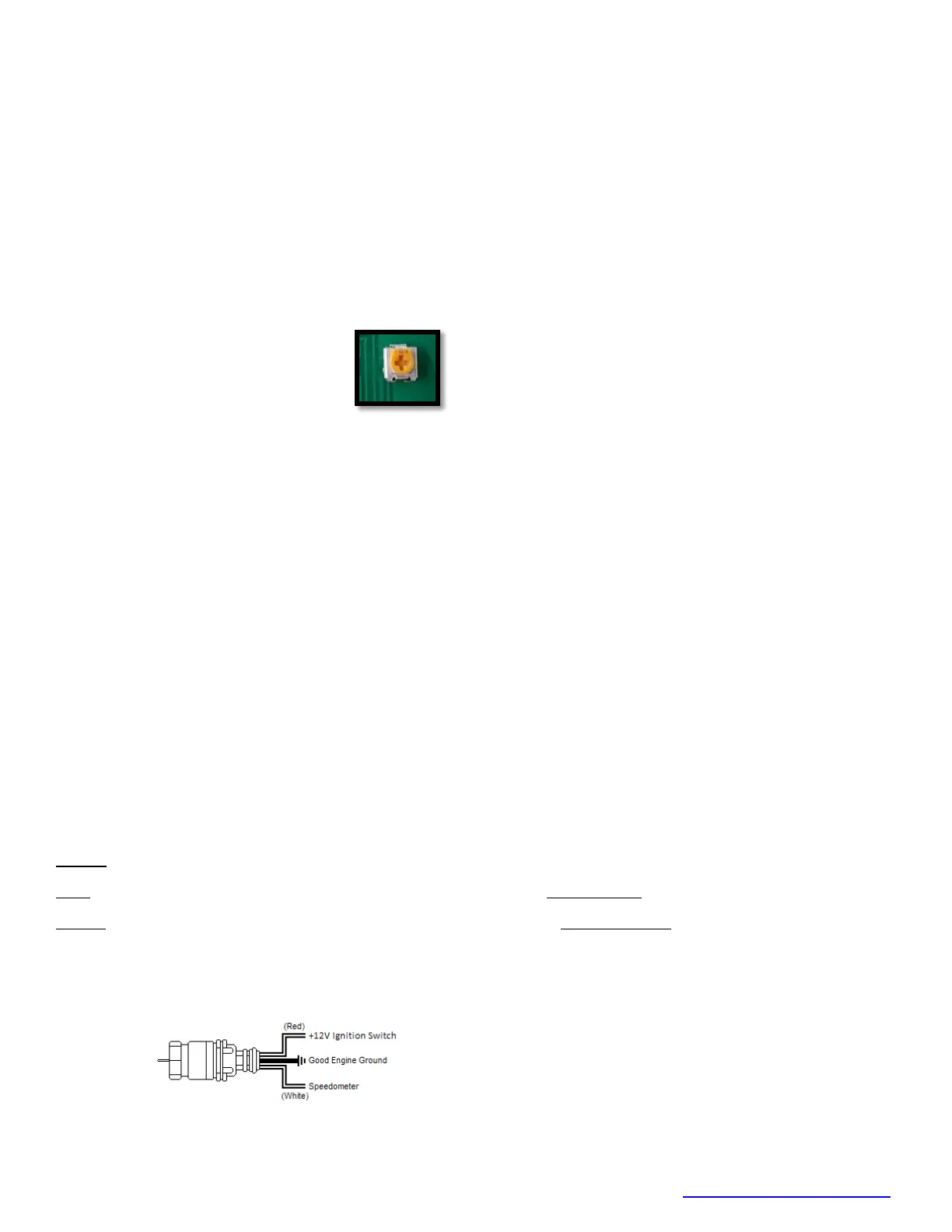
Speedometer - White (Intellitronix Speed Sender) - Disconnect the mechanical speedometer
cable from the transmission and thread the new electronic sensor onto the transmission. This
panel comes with a 3-wire sensor. If you are using this sensor you must fallow these wiring
instructions.
White -Wire is the speed signal; connect this to the speed signal wire on your gauge.
Red - Wires switch power (12VDC) and must be wired to Red/White on your Gauge.
Black - Wire is speed sensor ground and must be wired to Black/White on the Gauge.
NOTE:(Twist all Three wires together and this will provide an additional level of interference
protection.) The speed signal wire should not be routed alongside the tachometer, ignition, or
any other high-current or high-voltage wires
 Loading...