FM SECTION
1. IF ALIGNMENT
A. Set up the test equipment as Fig. 2-1.
B. Adjust the cross T604 and T605 so that the S curve developed on the oscilloscope become point
symmetry to the centry frequency poine of 10.7MHz with a maximum amplitude.
C. If the genescope is not available, set the unit detuned and adjust the cross of T604, T605 so that noise
output is maximized.
32
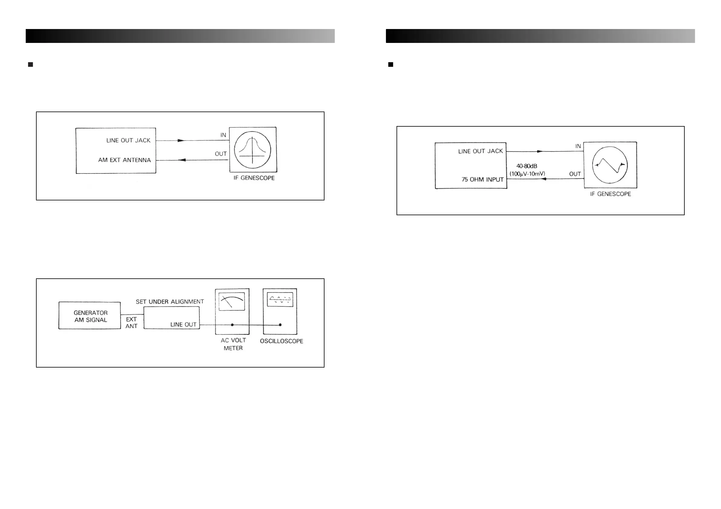
AM SECTION
1. IF ALIGNMENT
A. Set up the test equipment as Fig. 1-1 and set the genescope output level to 110dB (300mV).
B. Adjust T603 so that the figure developed or the oscilloscope become laterally symmetrical with the axis
of symmetry at 450kHz and it has a maximum amplitude as well.
2. RF TUNING ALIGNMENT
A. Set up the test equipment as Fig. 1-2.
B. Set AM SG to 30% modulation at 400Hz and 30-40dB output.
C. Set the up and down switch of the frequency display to 603 (or 600) kHz.
Adjust AM SG to 603 (or 600) kHz, adjust T602 (RF) to maximize audio frequency output level.
D. Set the up and down switch of the frequency display to 1404 (or 1400) kHz, adjust AM SG to 1404 (or
1400) kHz, and adjust AM trimmer capacitor C605 to maximize audio frequency output level.
E. Repeat steps and so that output is maximized at the given frequencies.
Fig. 1-1
Fig. 1-2