TEST 㞬ḱ㉔㉘㥉
8
ELECTRICAL ADJUSTMENT PROCEDURE (REAR PART)
ELECTRICAL ADJUSTMENT PROCEDURE (REAR PART)
9
PCM1738E
24-Bit, 192kHz Sampling,
Advanced Segment, Audio-Stereo
DIGITAL-TO-ANALOG CONVERTER
GGDESCRIPTION
GGFEATURE
The PCM1738 is a CMOS, monolithic, Integrated
Circuit (IC) that includes stereo Digital-to-Analog
Converters (DACs) and support circuitry in a small
SSOP-28 package. The data converters utilize a
newly developed advanced segment DAC architecture
to achieve excellent dynamic performance and
improved tolerance to clock jitter. The PCM1738
provides balanced current outputs, allowing the user to
optimize analog performance externally, and accepts
industry standard audio data formats with 16- to
24-bit data, providing easy interfacing to audio DSP
and decoder chips. Sampling rates up to 200kHz are
supported.
The PCM1738 also has two optional modes of
operation: an external digitalfilter mode
(for use with the DF1704, DF1706, and PMD200),
and a DSD decoder interface for SACD playback
applications. A full set of user-programmable
functions are accessible through a 4-wire serial control
port that supports register write and read functions.
½G24-BIT RESOLUTION
½ ANALOG PERFORMANCE (VCC = +5V):
Dynamic Range: 117dB typ
SNR: 117dB typ
THD+N: 0.0004% typ
Full-Scale Output: 2.2Vrms (at post amp)
½ DIFFERENTIAL CURRENT OUTPUT: ı 2.48mA
½ SAMPLING FREQUENCY: 10kHz to 200kHz
½ SYSTEM CLOCK: 128, 192, 256, 384, 512,
or 768fS with Auto Detect
½ ACCEPTS 16-, 20-, AND 24-BIT AUDIO DATA
½ DATA FORMATS: Standard, I2S, and Left-
Justified
½ 8x OVERSAMPLING DIGITAL FILTER:
Stopband Attenuation: –82dB
Passband Ripple: ı 0.002dB
½ OPTIONAL INTERFACE TO EXTERNAL
DIGITAL FILTER AVAILABLE
½ OPTIONAL INTERFACE TO DSD DECODER
FOR SACD PLAYBACK
½ USER-PROGRAMMABLE MODE CONTROLS:
Digital Attenuation: 0dB to –120dB, 0.5dB/Step
Digital De-Emphasis
Digital Filter Roll-Off: Sharp or Slow Soft Mute
Zero Detect Mute
Zero Flags for Each Output
½ DUAL-SUPPLY OPERATION:
+5V Analog, +3.3V Digital
½ 5V TOLERANT DIGITAL INPUTS
½ SMALL SSOP-28 PACKAGE
837
1MCP
24LC02B
2K I²C™ Serial EEPROM
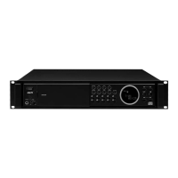
GGDESCRIPTION GGPACKAGE TYPE (SOIC)
GGFEATURE
GGPIN DESCRIPTION
• Single supply with operation down to 1.8V
• Low-power CMOS technology
- 1 mA active current typical
- 1µA standby current typical (I-temp)
• Organized as 1 block of 256 bytes (1 x 256 x 8)
• 2-wire serial interface bus, I²C™ compatible
• Schmitt Trigger inputs for noise suppression
• Output slope control to eliminate ground bounce
• 100 kHz (24AA02) and 400 kHz (24LC02B)
compatibility
• Self-timed write cycle (including auto-erase)
• Page write buffer for up to 8 bytes
• 2 ms typical write cycle time for page write
• Hardware write-protect for entire memory
• Can be operated as a serial ROM
• Factory programming (QTP) available
• ESD protection > 4,000V
• 1,000,000 erase/write cycles
• Data retention > 200 years
• 8-lead PDIP, SOIC, TSSOP and MSOP packages
• 5-lead SOT-23 package
• Pb-free finish available
• Available for extended temperature ranges:
- Industrial (I): -40°C to +85°C
- Automotive (E): -40°C to +125°C
The Microchip Technology Inc. 24AA02/24LC02B
(24XX02*) is a 2 Kbit Electrically Erasable PROM. The
operation down to 1.8V, with standby and active currents
has a page write capability for up to 8 bytes of data. The
available in the 5-lead SOT-23 package.
mount SOIC, TSSOP and MSOP packages and is also
with a 2-wire serial interface. Low-voltage design permits
24XX02 is available in the standard 8-pin PDIP, surface
of only 1µA and 1 mA, respectively. The 24XX02 also
device is organized as one block of 256x8-bit memory
2
0
XX
4
2
A0
A1
A2
Vss
1
2
3
4
8
7
6
5
Vcc
WP
SCL
SDA
PDIP/SOIC/TSSOP/MSOP
GGBLOCK DIAGRAM
HV
EEPROM
Array
Page
YDEC
XDEC
Sense Amp.
Memory
Control
Logic
I/O
Control
Logic
I/O
WP
SDA
SCL
V
CC
VSS
R/W Control
Latches
Generator
Name
A0
A1
A2
Vss
SDA
SCL
WP
PDIP SOIC TSSOP MSOP SOT23 Description
Vcc
11 11
22 22
33 33
-
-
-
44 442
55 55
66 66
77 77
88 88
3
1
5
4
Not Connected
Not Connected
Not Connected
Ground
Serial Address/Data I/O
Serial Clock
Write-Protect Input
அ1.8V to 5.5V Power Supply
 Loading...