Do you have a question about the Inter-m CM-20.5 and is the answer not in the manual?
Adjust VR101 for 10, 35, 45mA bias current based on measured voltage.
Adjust VR101/VR201 for 10mA idle current per channel.
Covers power output, frequency response, THD+N, and noise metrics.
Details sensitivity, gain, impedance, indicators, controls, and power specs.
Lists weight and dimensions of the amplifier models.
Lists components for CM5.5 amplifier and power boards.
Lists components for CM7.5/10.5 input and switch boards.
Lists components for CM7.5/10.5 amplifier and output boards.
Lists components for CM7.5/10.5 bracket and LED boards.
Lists components for CM15.5/20.5 input and power boards.
List of components for CM15.5/20.5 switch board.
List of components for CM7.5/10.5 bracket board.
Visual layout of the CM5.5 amplifier board.
Visual layout of the CM5.5 power board.
Visual layout for M-700/1000 amplifier board.
Visual layout for CM15.5/20.5 amplifier board.
Visual layout for M500 amplifier board.
Visual layout for M-700/1000 power board.
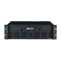
Visual layout for M-1500/2000 power board.
Visual layout for CM5.5 switch board.
Visual layouts for CM7.5/10.5 bracket and switch boards.
Visual layouts for CM15.5/20.5 switch and bracket boards.
Wiring diagram for the CM5.5 amplifier model.
Wiring diagram for the CM7.5/10.5 amplifier models.
Overall functional block diagram of the amplifier system.
Wiring diagram for the CM15.5/20.5 amplifier models.
Detailed schematic diagram for the CM 5.5 amplifier.
Detailed schematic diagram for CM7.5/10.5 models.
Detailed schematic diagram for CM15.5/20.5 models.
Mechanical components for CM-5.5 model.
Mechanical components for CM-7.5/10.5 models.
Mechanical components for CM-10.5 (DOM).
Mechanical components for CM-5.5/7.5 (DOM).
Mechanical components for CM-15.5 model.
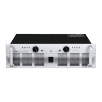
Mechanical components for CM-20.5 model.
Assembly drawing of the front panel for CM-5.5/7.5/10.5.
Assembly drawing of the top cover and related parts.
Assembly details of various input/output connectors.
Assembly details for AC cord and circuit breaker.
Assembly drawing of the front panel for CM-15.5/20.5.
Assembly drawing of the back chassis and related parts.
| Type | Power Amplifier |
|---|---|
| Channels | 2 |
| Power Output (per channel) | 20W |
| Frequency Response | 20Hz - 20kHz |
| Input Impedance | 10kΩ |
| Power Source | AC 50/60Hz |