EasyManua.ls Logo

Inter-m M-1500 - User Manual

Inter-m M-1500
20 pages
Print Icon
To Next Page IconTo Next Page
Loading...
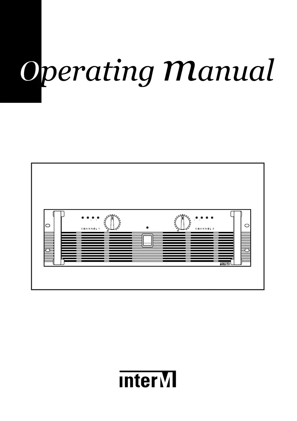
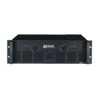
M-1500/2000
Power Amplifier
POWER
4
0
d
B
P
R
O
T
C
L
IP
4
0
d
B
2
0
d
B
2
0
d
B
C
L
IP
P
R
O
T
POWER AMPLIFIER
M
2000
17
22
13
10
0
1
229
54
19
15
11
12
9
8
7
5
4
3
6
17
22
13
10
0
1
229
54
19
15
11
12
9
8
7
5
4
3
6

Other manuals for Inter-m M-1500

Questions and Answers

  • J
    jacob94Jul 31, 2025
    What to do if the CLIP indicator lights on my Inter-m M-1500 Amplifier?
    • D
      Desiree ColeJul 31, 2025
      If the CLIP indicator lights on your Inter-m Amplifier, it means the amplifier load is excessive. To resolve this, use a speaker system with an impedance of at least 4 Ohms (stereo) or 8 Ohms (bridge).
  • M
    Matthew MartinezAug 11, 2025
    Why does the PROTECTION indicator light turn on on my Inter-m M-1500?
    • M
      Monica FisherAug 11, 2025
      If the PROTECTION indicator lights on your Inter-m Amplifier, it could be due to the heat sink temperature exceeding 100°C. Ensure proper ventilation around the amplifier to improve airflow.
  • J
    Jeremiah PittmanAug 19, 2025
    How to fix '-40dB indicator lights only' issue on Inter-m M-1500?
    • C
      Cheryl TaylorAug 19, 2025
      If the –40dB indicator is the only light that is on on your Inter-m Amplifier, it indicates a short at a speaker terminal, amplifier terminal, or wire. You should locate and correct the cause of the short.

Summary

Unpacking and Installation

Amplifier Features

Key Features Overview

Details protection, mono operation, displays, compact design, cooling, connectivity, and transformer.

Front Panel Controls

Front Panel Indicators and Controls

Describes protection, clip, level indicators, input attenuators, power switch, and handles.

Rear Panel Controls

Rear Panel Components

Details fans, circuit breaker, and output terminals.

Rear Panel Connectivity

Input Terminals, AC Inlet, and Mode Selector

Details input jacks, AC inlet, and the mode selector switch for rear panel setup.

Protection Circuitry

Causes for Protection Activation

Lists conditions like overheating, overcurrent, shorts, impedance issues, and DC voltage.

Bridged and Parallel Modes

Connection Diagrams

Stereo, Bridged, and Parallel Wiring

Illustrates speaker and input wiring for stereo, bridged mono, and parallel modes.

Link Connectors

Speaker Impedance Guidelines

Speaker Connection Precautions

Speaker Fuse Protection

Recommends using a serial fuse to protect speakers if their capacity is lower than amplifier output.

Portable Rack Mounting

Speaker Cable Best Practices

Advises using thick cables for long runs to maintain signal integrity and damping factor.

Amplifier Placement and Ventilation

Troubleshooting Common Issues

System Block Diagram

Technical Specifications

Inter-m M-1500 Specifications

General IconGeneral
BrandInter-m
ModelM-1500
CategoryAmplifier
LanguageEnglish

Related product manuals