EasyManua.ls Logo

Inter-m M-2000 User Manual

Inter-m M-2000
20 pages
To Next Page IconTo Next Page
Page #1 background imageLoading...
Page #1 background image
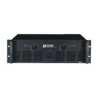
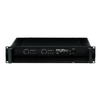
M-1500/2000
Power Amplifier
POWER
4
0
d
B
P
R
O
T
C
L
IP
4
0
d
B
2
0
d
B
2
0
d
B
C
L
IP
P
R
O
T
POWER AMPLIFIER
M
2000
17
22
13
10
0
1
229
54
19
15
11
12
9
8
7
5
4
3
6
17
22
13
10
0
1
229
54
19
15
11
12
9
8
7
5
4
3
6

Other manuals for Inter-m M-2000

Questions and Answers:

Inter-m M-2000 Specifications

General IconGeneral
BrandInter-m
ModelM-2000
CategoryAmplifier
LanguageEnglish

Summary

Unpacking and Installation

Electrical Safety Precautions

Essential safety guidelines for handling the amplifier, preventing electric shock, fire, and moisture damage.

Features

Front Panel Controls Overview

Protection Indicator LED

Monitors protection system status during power-up and operation, indicating potential issues.

Clip Indicators

Warns of signal distortion by illuminating when input levels cause clipping.

Output Level Indicators

Visual feedback on the amplifier's output signal strength, showing levels at -40dB and -20dB.

Input Attenuators

Adjustable controls for precise setting of input signal levels for each channel.

Power Switch and Indicator Light

Main power control and status light, indicating when the amplifier is active.

Amplifier Handles

Integrated handles designed for safe and convenient carrying and positioning.

Rear Panel Controls and Connections

Cooling Fans

Ventilation fans ensuring optimal thermal management; keep unobstructed for airflow.

Circuit Breaker Reset

Protective device to reset after overload or error, safeguarding the unit from power issues.

Speaker Output Terminals

Binding posts and Speakon connectors for reliable speaker connections in various modes.

Protection Circuitry Explained

Initial Power-Up Protection

Mutes speaker output for ~5 seconds at startup to prevent audible thumps and protect components.

Overheating Protection

Activates if internal temperature exceeds safe limits, ensuring unit longevity.

Overcurrent Protection

Triggered by excessive signal distortion (THD > 20%) to safeguard power transistors.

Shorted Speaker Cable Protection

Detects and reacts to short circuits in speaker wiring, preventing damage.

Low Impedance Protection

Activates if connected speaker impedance drops below 2 ohms, preventing overload.

DC Output Voltage Protection

Responds to DC voltage at the output, typically indicating an internal fault.

Bridged and Parallel Mode Operation

Bridged Mono Mode

Combines amplifier channels for enhanced power output into an 8-ohm load.

Parallel Mono Mode

Outputs Channel 1 signal to both channels for dual mono operation into 4-ohm loads.

Interconnecting Amplifiers (Link Connectors)

Understanding Speaker Impedance

Speaker Connection Cautions

Speaker Fuse Protection

Recommended method for installing a fuse to protect speakers from amplifier output.

Portable Rack Mounting Guidelines

Housed Amplifier Placement

Troubleshooting Amplifier Issues

Common Indicators and Solutions

Guide to interpreting indicator lights and resolving common operational problems.

Amplifier Block Diagram

Technical Specifications Summary

Related product manuals