9
M-1500/2000
POWER AMPLIFIER
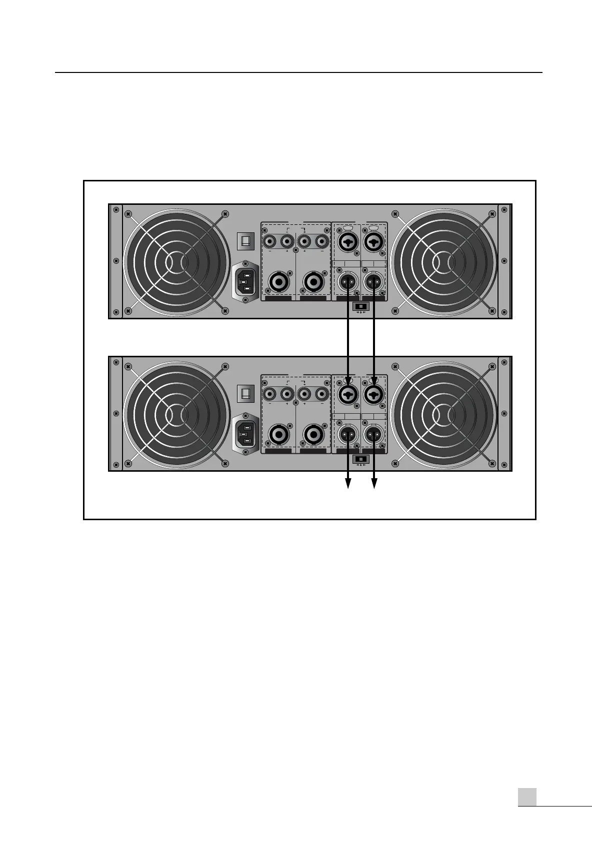
Link Connectors
The illustration belows shows how multiple amplifiers can be interconnected using the M-1500/2000 link
connectors.
Speaker Impedance
Link Connectors
The illustration belows shows how multiple amplifiers can be interconnected using the M-1500/2000 link
connectors.
Speaker Impedance
M-1500/2000 series amplifier has three operating modes: Stereo, Bridged and Parallel and allows you to
connect multiple speaker systems in parallel. Therefore, the minimum speaker impedance various depend-
ing on the combination of these speakers. Be sure that the speaker impedance falls below the specified
impedance.
The 8 page show the examples of connection is Stereo mode and Bridged mode, and speaker systems con-
nected in parallel in Stereo mode, and the respective minimum impedance.
PUSH TO RESET
20A / 250V
(4Ω ~ 8Ω)(4Ω ~ 8Ω)
BRIDGED
(8Ω~16Ω)
(4Ω ~ 8Ω)(4Ω ~ 8Ω)
CH 1CH 2
OUTPUT
BALANCED
0dBm
BALANCED
0dBm
CH 1CH 2
~AC INPUT
230V 50Hz, 1300W
STEREO
BRIDGED
PARALLEL
INPUT
XLR
BALANCED
•3=COLD
•2=HOT
•1=GND
•TIP=HOT
•RING=COLD
•SLEEVE=GND
TRS
BALANCED
PUSH PUSH
PUSH TO RESET
20A / 250V
(4Ω ~ 8Ω)(4Ω ~ 8Ω)
BRIDGED
(8Ω~16Ω)
(4Ω ~ 8Ω)(4Ω ~ 8Ω)
CH 1CH 2
OUTPUT
BALANCED
0dBm
BALANCED
0dBm
CH 1CH 2
~AC INPUT
230V 50Hz, 1300W
STEREO
BRIDGED
PARALLEL
INPUT
XLR
BALANCED
•3=COLD
•2=HOT
•1=GND
•TIP=HOT
•RING=COLD
•SLEEVE=GND
TRS
BALANCED
PUSH PUSH
TO ADDITIONAL AMPLIFIERS