4
M-1500/2000
POWER AMPLIFIER
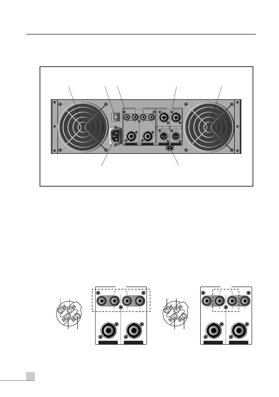
Rear Panel Controls
Rear Panel Controls
1. FANS
The fans should be kept free of all obstructions and be accessible to cool fresh air when possible. It is
important that the fans be used in a dust free environment.
2. CIRCUIT BREAKER
When the circuit breaker is cut, push to reset again. In case of occuring trouble to the set by means of
overload or error, circuit breaker will protect the set from trouble by breaking AC power source.
3. OUTPUT TERMINALS
Output terminals are dual five-way binding posts and speaker connectors. Do not parallel the two out-
puts of each channel by connecting them (together, or parallel them) with any other amplifier output.
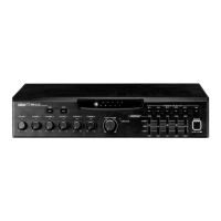
* When speakers are connected through speaker, please make sure correct connection of each pin, and
refer speaker pin number.
- STEREO MODE - BRIDGED MODE
The minimum impedance for the connected speaker system is specified in “Speaker Impedance” on page 6.
PUSH TO RESET
20A / 250V
(4Ω ~ 8Ω)(4Ω ~ 8Ω)
BRIDGED
(8Ω~16Ω)
(4Ω ~ 8Ω)(4Ω ~ 8Ω)
CH 1CH 2
OUTPUT
BALANCED
0dBm
BALANCED
0dBm
CH 1CH 2
~AC INPUT
230V 50Hz, 1300W
STEREO
BRIDGED
PARALLEL
INPUT
XLR
BALANCED
•3=COLD
•2=HOT
•1=GND
•TIP=HOT
•RING=COLD
•SLEEVE=GND
TRS
BALANCED
PUSH PUSH
6
5
1 2431
1- 1+
2+ 2-
AMP OUTPUT CH1, CH2
NOT CONNECTED
(4Ω ~ 8Ω)(4Ω ~ 8Ω)
BRIDGED
(8Ω~16Ω)
(4Ω ~ 8Ω)(4Ω ~ 8Ω)
CH 1CH 2
OUTPUT
1- 1+
2+ 2-
MONO(BTL)
CH1 OR CH2
NOT CONNECTED
(4Ω ~ 8Ω)(4Ω ~ 8Ω)
BRIDGED
(8Ω~16Ω)
(4Ω ~ 8Ω)(4Ω ~ 8Ω)
CH 1CH 2
OUTPUT