Do you have a question about the Inter-m PA-2312 and is the answer not in the manual?
Avoid high levels of heat, dust, moisture, and vibration for optimal performance and service life.
Key safety guidelines for installation and operation, including handling water and electrical hazards.
Information on provided accessories, specifically the detachable AC power cord.
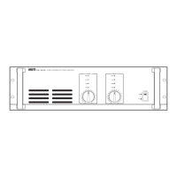
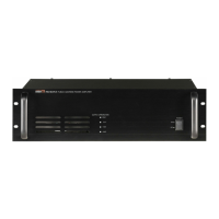
LED indicating the status of the amplifier's protection circuitry; active when not operating normally.
LEDs showing output status; red CLIP LED indicates excessive output level.
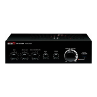
Button to turn the unit on or off. Pushing up turns it on, pushing down turns it off.
Indicator light that glows steadily when the unit is powered on.
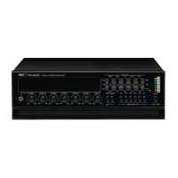
Controls for regulating each channel's output level; clockwise rotation increases gain.
Connection point for the standard AC input cable.
Terminals for connecting speakers; impedance must be equal to or higher than rated.
Vents for hot air outflow; keep unobstructed and operate in a dust-free environment.
Contains the AC overload protection fuse; replace with same type/rating if blown.
Activates a filter to reduce low frequencies, protecting speakers and components.
Balanced input connectors provided on both male and female XLR jacks for convenience.
Connects/disconnects amplifier ground to AC earth ground to prevent noise from ground loops.
Terminals for connecting a 24VDC battery source for backup power.
Details electrical characteristics like rated output, sensitivity, THD, S/N, and channel separation.
Details general specifications including power source, consumption, weight, and dimensions.
Steps to follow if a problem occurs, recommending checking external devices and consulting warranty provider.
Information on how to obtain a schematic diagram for service purposes.
Information on how to obtain a parts list for service or replacement.
Details on product variations, noting compatibility with local AC power requirements.
Information regarding optional items; states that no optional items are available for this product.
| Type | Power Amplifier |
|---|---|
| Input Sensitivity | 1V |
| Frequency Response | 20Hz - 20kHz |
| Total Harmonic Distortion (THD) | 0.1% |
| Signal-to-Noise Ratio | >100dB |
| Output Impedance | 4Ω |
| Power Source | AC 220V |
| Input Impedance | 10kΩ |
| Damping Factor | >200 |
| Dimensions | 482(W) x 88(H) x 380(D) mm |