1
1. CM-7.5/10.5/15.5/20.5
IDLE CURRENT
A. Setting
Set the master volume control minimum.
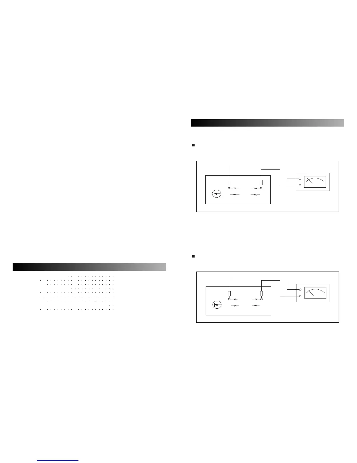
B. Connection
C. Adjustment
Adjust VR101 so that the current through the R158 and R140 become 10, 35, 45 milliampere.
When that voltage is;
6~12 millivolt, the current becomes 10 milliampere (CM-7.5, CM-10.5)
30~40 millivolt, the current becomes 35 milliampere (CM-15.5)
40~50 millivolt, the current becomes 45 milliampere (CM-20.5)
2. CM-5.5
IDLE CURRENT
A. Setting
Set the master volume control minimum.
B. Connection
C. Adjustment
Adjust VR101 for CH1 so that the current through the R158 and R140 become 10 milliampere.
Adjust VR201 for CH2 so that the current through the R258 and R240 become 10 milliampere.
When that voltage is 6~12 millivolt, the current becomes 10 milliampere.
ELECTRICAL ADJUSTMENT PROCEDURE
Electrical Adjustment Procedure 1
Specifications
2
Electrical Parts List
3, 4, 5, 6, 7, 8
Top and Bottom View of P.C. Board
9, 10, 11, 12, 13, 14, 15, 16, 17
Wiring Diagram 18, 19, 20
Block Diagram 21
Schematic Diagram 22, 23, 24, 25, 26, 27
Exploded View of Cabinet & Chassis / Mechanical Parts List
28, 29, 30, 31
Ass’y Drawing
32, 33, 34, 35
CONTENTS