PROFESSIONAL POWER AMPLIFIER
10
L800/1400/1800/2400/3000
English
Connections
Inter-M products are wired according to professionally accepted wiring practices used throughout the world.
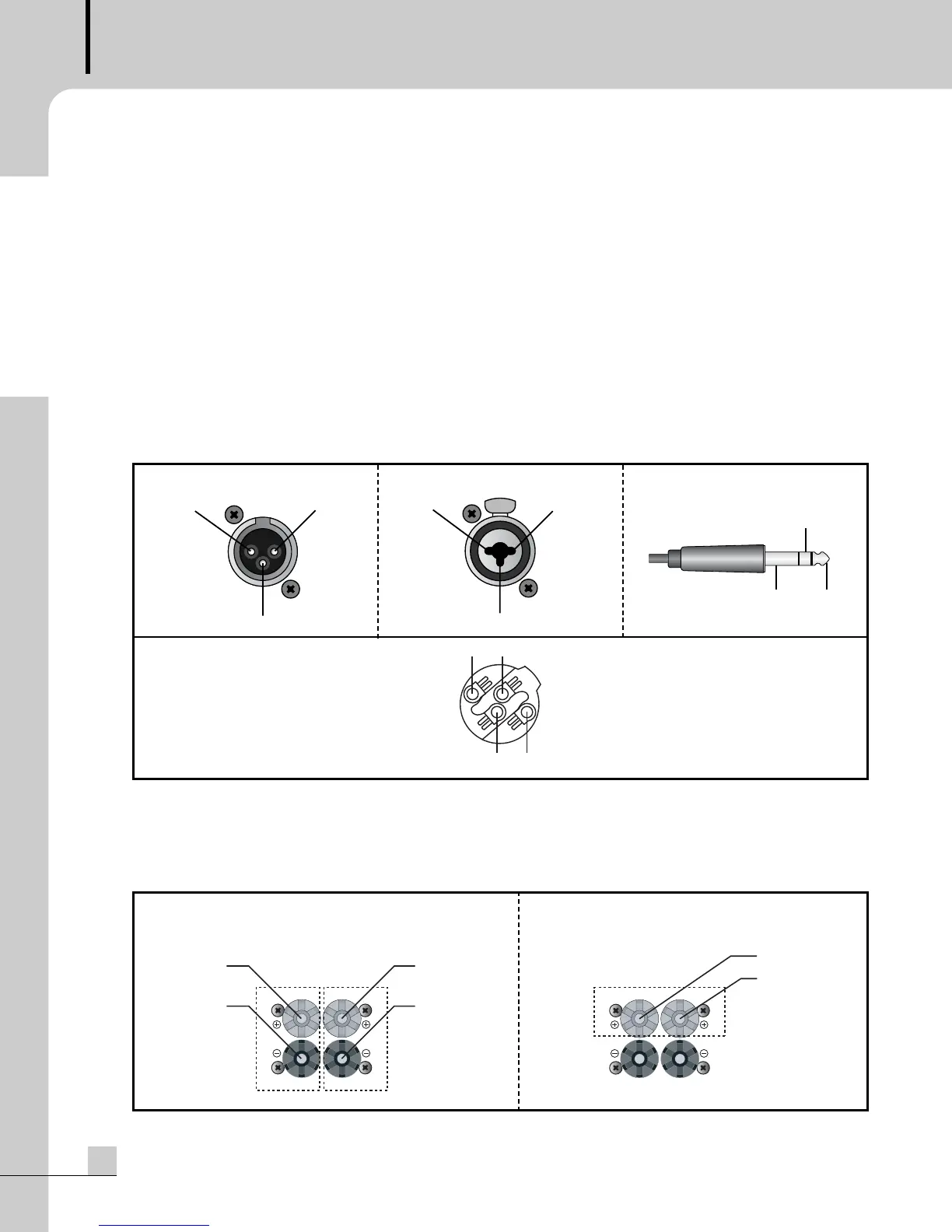
Balanced XLR connectors are wired as described:
Pin #1 shield
Pin #2 Positive
Pin #3 Common
Balanced 1/4” TRS connectors are wire as described:
Tip is Positive
Ring is Common
Sleeve is Shield
The combination connector is designed to accept either the XLR or the 1/4” TRS Phone Jack
Stereo operation uses the + (positive) and the – (negative) terminal from each set of channel output binding
posts. (CH1 : 1+, 1- /CH2 : 2+, 2-)
Bridged Mono uses the + (positive) terminal of both channels only. The – (negative) terminals have no
connection. Bridged Mono operation has a minimum load impedance of 4Ω.
- XLR MALE
- COMBINATION
- SPEAKON CONNECTOR
Pin set #1
Wiring Diagram
- PHONE JACK