Operating Instructions
4/8-indent crimping tool CO.236.00
Rev.: 2015-10-16 5 / 12
EN
Standard mm
Inch
MIL selector
positions
Setting the crimping parameters
· Crimp indenter setting and locator (3) position can be found on the setting matrix. The
values for the matrix were determined by using fine copper stranded wire. The values
are merely a guideline and have to be checked by the user, if the pull-out forces conform
at minimum to DIN EN 60352-2 standard (table4).
· Refer to the adjustment matrix for die settings and locator positions (3) for the
contact you intend to crimp.
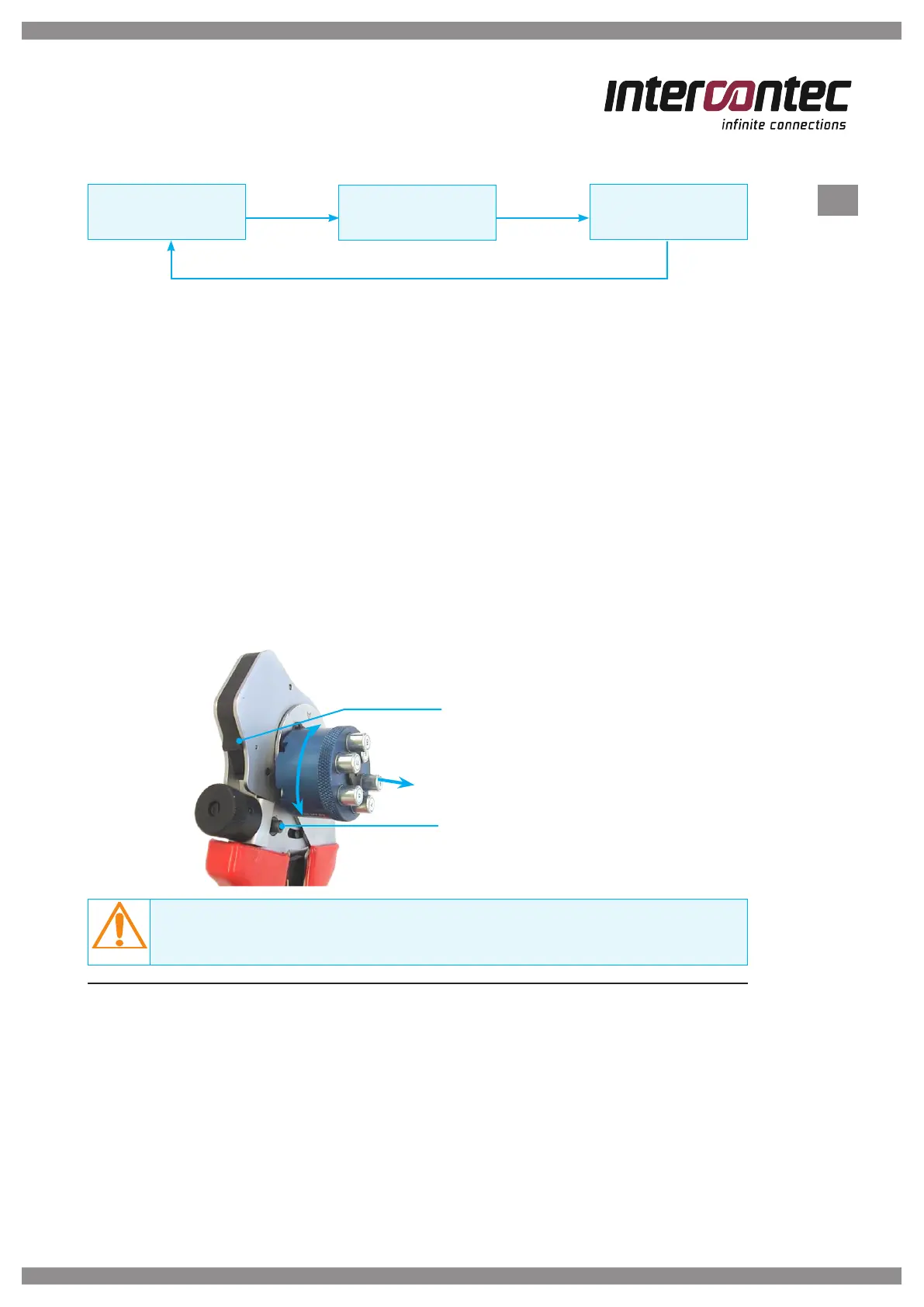
· Change the crimping die setting (crimping die depth) by turning the adjustment wheel
until the digital display shows the desired value.
· Lock the crimper setting using the locking screw (2).
· Lift and turn the locator (3) to the side (see Figure 2) into the setting shown on
the adjustment matrix and push the locator cartridge in place.
NOTE
Always set the crimper depth from a larger value, such as from 2.05 mm to 2 mm.
3 Crimping procedure
· Feed the prepared cable into the connector.
· Lay the contact with the cable into the crimper's crimping point until it will not go
any further; the locator will position the contact exactly.
· Close the crimper until unlocking via the catch.
· Open the crimper and remove the crimped contact.
Type CR 2025 battery compartment
Clamping screw
for locking the crimper setting
Figure 2