3 / 9© INTEREL 2021 - rev07
Installation
Location
Select a location about 1.5m (5ft) above the oor and with
good air circulation at average temperature. Do not mount
the thermostat where it may be aected by:
• Drafts or dead spots behind doors or in corners
• Hot or cold air from ducts
• Radiant heat from sun or appliances
• Pipes or chimneys
• Unheated or uncooled areas behind the thermostat
• RF sources or transmitters
For accurate presence detection using the built-in PIR sen-
sor, consider the sensor’s view angle, range characteristics
and thermostat mounting position.
Mounting
The INTEREL EOS Thermostat is designed to be surface
mounted, and therefore can be installed in almost any sce-
nario found in a hotel guestroom. Typically, the EOS ther-
mostat will be mounted on a (4x4) double-gang junction
box. If mounted on a single-gang junction box, the 24 Vac
power or 100–277 Vac power and signal wires connecting
CN2 to the HVAC equipment must reside in the single-gang
box, and the low voltage signal wires connected to CN1 re-
side on the left side overlapping the wall area. A low voltage
mud ring, or low voltage caddy may be used for mounting
the 24V AC EOS Thermostat.
Before beginning work, ensure that the supply power
(24 Vac or 100-277 Vac) is turned o and secured. If an
existing thermostat is being replaced, remove the ther-
mostat and note the function of each wire if not already
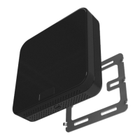
documented. Position the EOS Metal Wall Bracket with
raised arrows pointing UP and mount it to the junction
box using the (4) provided screws. The installation area
behind the bracket must be at and free from debris to
allow the Metal Wall Bracket to sit at on the wall. Adjust
the bracket position to be level before fully tightening
the screws. Do not over tighten the screws, which may
result in a loose connection to the EOS Thermostat.
Remove the CN1 and CN2 connectors from the back of
the thermostat by prying them out gently with a at
head screwdriver. Then prepare the power and control
wiring coming from the HVAC equipment and connect
the appropriate wires to their respective terminals on
the CN1 and CN2 connectors (refer to the property and
HVAC equipment wiring diagrams).
Insert the CN1 and CN2 connectors back into EOS, veri-
fying that they are fully seated for a secure connection.
When mixed voltages are used on the CN1 and CN2
connectors, a voltage separator must be installed per
local electrical code regulations. Line voltage must re-
side in the right side of the junction box and low volt-
age must reside in the left side of the junction box.
Installation Instructions
CAUTION: Disconnect the power supply before installation to pre-
vent electrical shock or equipment damage. All wiring must comply
with local codes and ordinances.
• Read the instructions carefully. Failure to follow them could damage the product or create a hazard.
• Check the ratings given in the EOS datasheet and on the product to ensure the product is suitably rated
for the application.
• The installer must be a trained, experienced HVAC technician.
• After installation is complete, check product operation as indicated in the instructions.
1.
2.
3.
 Loading...